

Hi all,
I'm working on implementing 1-wire bus between two CC2531 USB dongles. For that matter the first thing I am trying to work out is make one of them pull down the line to trigger an interrupt on the other dongle. That is:
-Master configuration: pin 1.4 as input, INT enabled, no pullups. By default the input will be high, until the slave pulls down the line.
-Slave configuration: pin 1.4 as output, no pullups. When I press SW1 it should put output LOW.
Master code:
/**** Turn on global interrupts. ****/
  HAL_ENABLE_INTERRUPTS();
  IEN2 = 0x10;        //Enable interrupts on Port 1
  P1IFG = 0;          // clear all interrupt flags for P1
  P1DIR &= 0x02;      // set bit as input
  PICTL |= 0;         // enable interrupt on Bit

  P1IFG &= ~BV(4);    // clear interrupt flag
  P1IEN |= BV(4);     // enable P1_4 interrupt
  P1INP = 0xFC;       //Disable internal pullups on P1 port
  HAL_TURN_ON_LED1();

  for(;;) {

  }
HAL_ISR_FUNCTION( HalIntExt, P1INT_VECTOR )

{

  P1IFG =0;  //clear flags P1
  P1IF = 0;  //clear flags P1

  HAL_TURN_OFF_LED1();

}
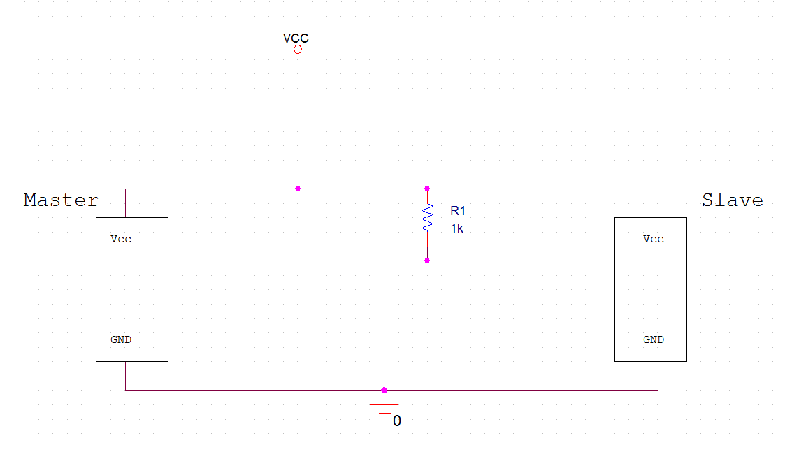
I attach part of the code (what I think it is failing) and the basic setup on the protoboard.
My problem is: If I test the master individually bringing the line to GND manually, it does work, the master sees the edge and interrupts. On the other hand, the slave works individually and brings the line down putting a LOW on the output. When I mount them together it does not work.
Slave code:
/**** Turn on global interrupts. ****/
  HAL_ENABLE_INTERRUPTS();
  IEN2 = 0x10;  //Enable interrupts on Port 1
  P1IFG = 0;    //clear all interrupt flags for P1
  P1DIR = 0x10; //SW1 as input and P1.4 as output
  PICTL |= 0;   // enable interrupt on Bit

  P1IFG &= ~BV(2);    // clear interrupt flag
  P1IEN |= BV(2);     // enable P1.2 interrupt
  P1INP = 0xFC;       //Disable pullups on P1 port
  HAL_TURN_ON_LED1();

  for(;;) {

  }
HAL_ISR_FUNCTION( HalIntExt, P1INT_VECTOR )

{
  P1IFG =0;  //clear flags P1
  P1IF = 0;  //clear flags P1

  HAL_TURN_OFF_LED1();
  P1_4 = 0;
}
Do you people see anything wrong?
Frankly I appreciate your help
