This thread has been locked.

If you have a related question, please click the "Ask a related question" button in the top right corner. The newly created question will be automatically linked to this question.

CC2538 external 32 MHz crystal problem

Other Parts Discussed in Thread: CC2538, Z-STACK, CC2530

I use http://www.mouser.com/ds/2/122/ECX_42-12562.pdf 

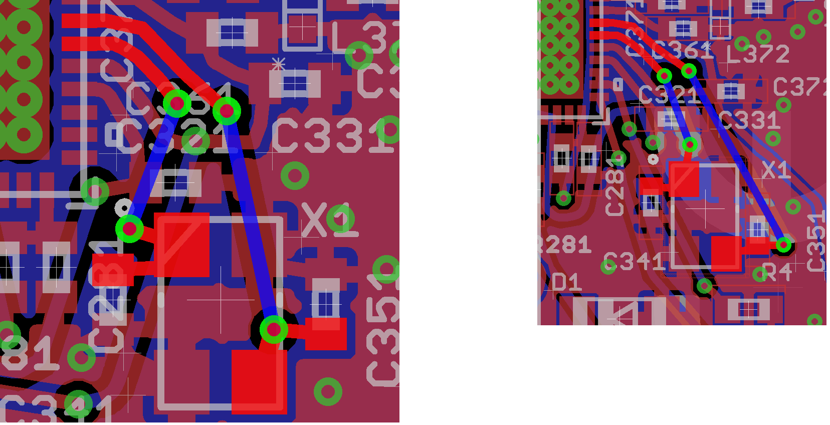
The right layout is an older version of my board which totally works fine. The left one is the newer version where I placed the components closer to each others (as well as the crystal). However, the 32 MHz crystal does not work properly on the new board ( I carefully assembled three of them).

I measured the pins of crystal by an oscillator, and I see the logic level of pins goes a higher, but don't oscillate. In addition, my code gets stuck on externalclock initialization (BoardInit() ).

Does anyone see any possible problem or have any suspicion or have any suggestion to debug/solve the problem?

What I did so far to debug the problem is that:

  • I replaced the crystal and load caps with the new ones and the ones from the old board that works for sure. It didn't help
  • pins of the crystals are measured by an oscillator, but there is no oscillation on the pins (the board has a 32k crystal as well, that one works fine).
  • I tested the same SW on CC2538EM, so that the SW works correctly and it should be a HW problem.
  • The orientation of the crystal is assembled correctly for sure, I use known brand capacitors (Murata and Kemet).
  • I inspected crystal's path to the MCU by a microscope and the solder on the pins looks fine.

Additionally, I use 20 pF for C341 and C351 caps

  • Hi,
    I reviewed the crystal specs and it meets the CC2538 requirement.
    Did you test this crystal on your old board or on CC2538EM?
    Do have Scope/Spectrum Analyzer to test the Osc frequency?
    Did you get the correct frequency (32MHz) crystal?
    Measure the resistance in between the Crystal pin and crystal case. It should be high. Some times, if the assembly is not good, it may short to Ground.
    Measure the continuity in between the Crystal pins and CC2538 pins for any open circuit.
    First make sure the Crystal is oscillating. you may test it on CC2538EM.

    Thanks,
    PM
  • Hi PM,

    Thank you for the reply. 

    I did all of them. No short circuit on the layout or after the assembly. I clean my board against the flux residues.

    When I measure the 32MHz crystal's pins, one pin was on logic high, but wasn't oscillating. Then I added 1M ohm parallel to the input/output pins to create imbalance. As a result, the crystal started working. However, I still couldn't understand why the crystal works on the old board without need of any additional resistor but it needs on the new board. 

    Before adding the resistor, my code was getting stuck on the ROM area. After adding the resistor, the program flows normally. But, I still have a problem. 

    I have three identical custom boards. One works fine and I see its radio output signal on the CC2530 sniffer; the second one gets stuck on MAC timer start on the code and not radio output;  the last one's code flows without any problem, however, it does not transmit any radio packet (I use the same SW, Z-stack generic App, on the boards).

    I measure the oscillation frequency of the crystal as 32 MHz on three boards. Do you have any guess why the program would not be able to start the MAC timer or the program flows normally but it does not output any TX signal? Is there any definition on Z-stack that if the frequency's ppm is more than 40 ppm, then TX interface would not work?

  • Hi,

    Did you try with changing the load cap values (without adding resistors)?

    Our software team will respond to your other queries.

    Thanks,
    PM
  • I am using 18 pF on the design, I replaced it with 15pF, 20pF, 22pF, and 27pF but none of them helped.
  • Hello,

    are you using Contiki?
    in Contiki application is the bootloader active.
    #ifndef FLASH_CCA_CONF_BOOTLDR_BACKDOOR
    #define FLASH_CCA_CONF_BOOTLDR_BACKDOOR 0 /**<Enable the boot loader backdoor */
    #endif

    #ifndef FLASH_CCA_CONF_BOOTLDR_BACKDOOR_PORT_A_PIN
    #define FLASH_CCA_CONF_BOOTLDR_BACKDOOR_PORT_A_PIN 3 /**< Pin PA_3 (Select button) activates the boot loader */
    #endif

    #ifndef FLASH_CCA_CONF_BOOTLDR_BACKDOOR_ACTIVE_HIGH
    #define FLASH_CCA_CONF_BOOTLDR_BACKDOOR_ACTIVE_HIGH 0 /**< A logic low level activates the boot loader */
    #endif

    if there is no correct Signal on PA3 the controller will enter Bootloader and on debugger it looks like the controller stucks in code..