This thread has been locked.

If you have a related question, please click the "Ask a related question" button in the top right corner. The newly created question will be automatically linked to this question.

CC2530 power down timing

Other Parts Discussed in Thread: CC2530

Hi,

The datasheet for CC2530 states that PM1 is to be used for sleep times below 3ms, as it uses a fast power-up and power-down sequence. I can see no differences between PM1 and PM2 in regards to power down time.

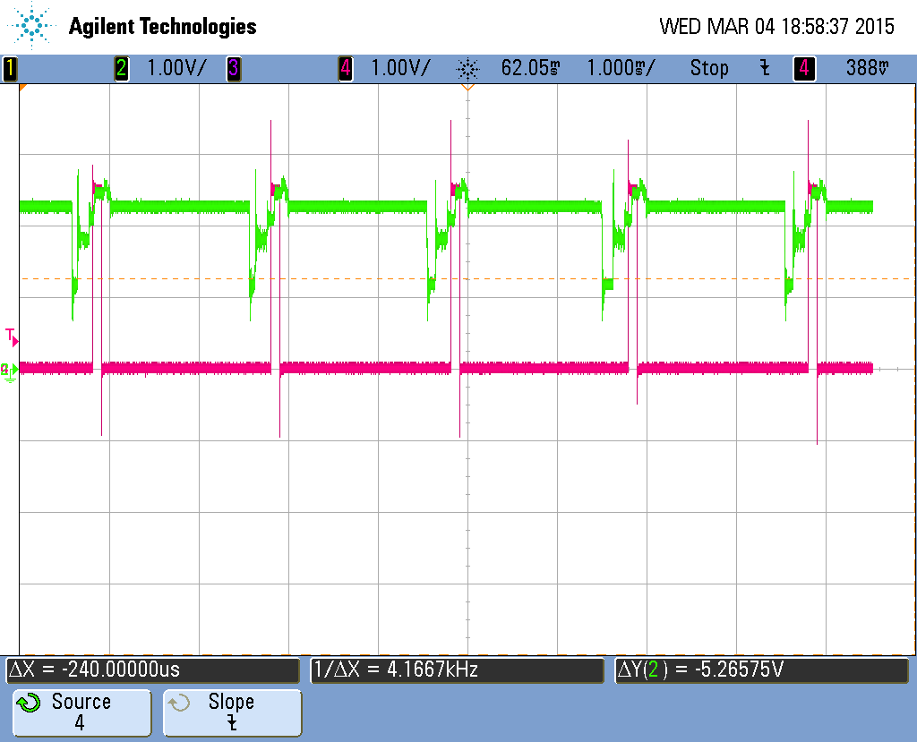
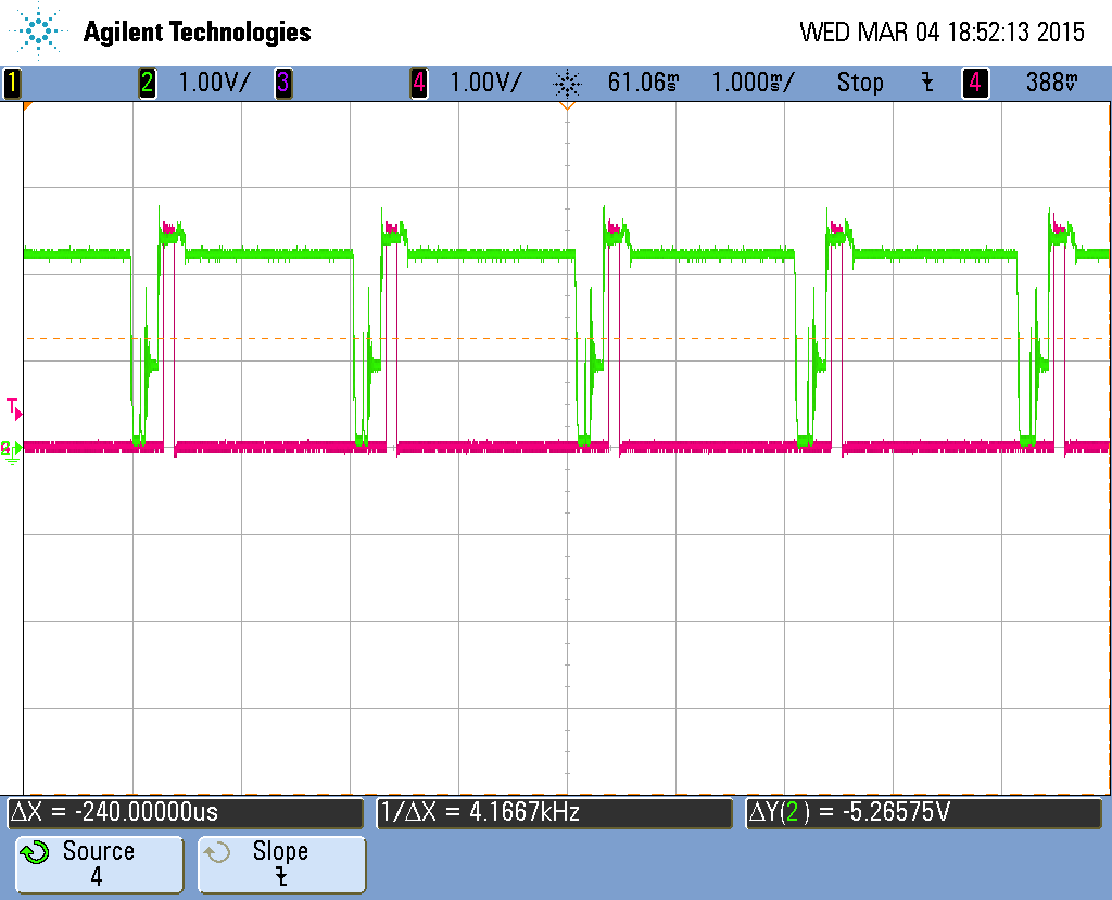
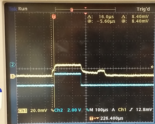
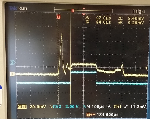
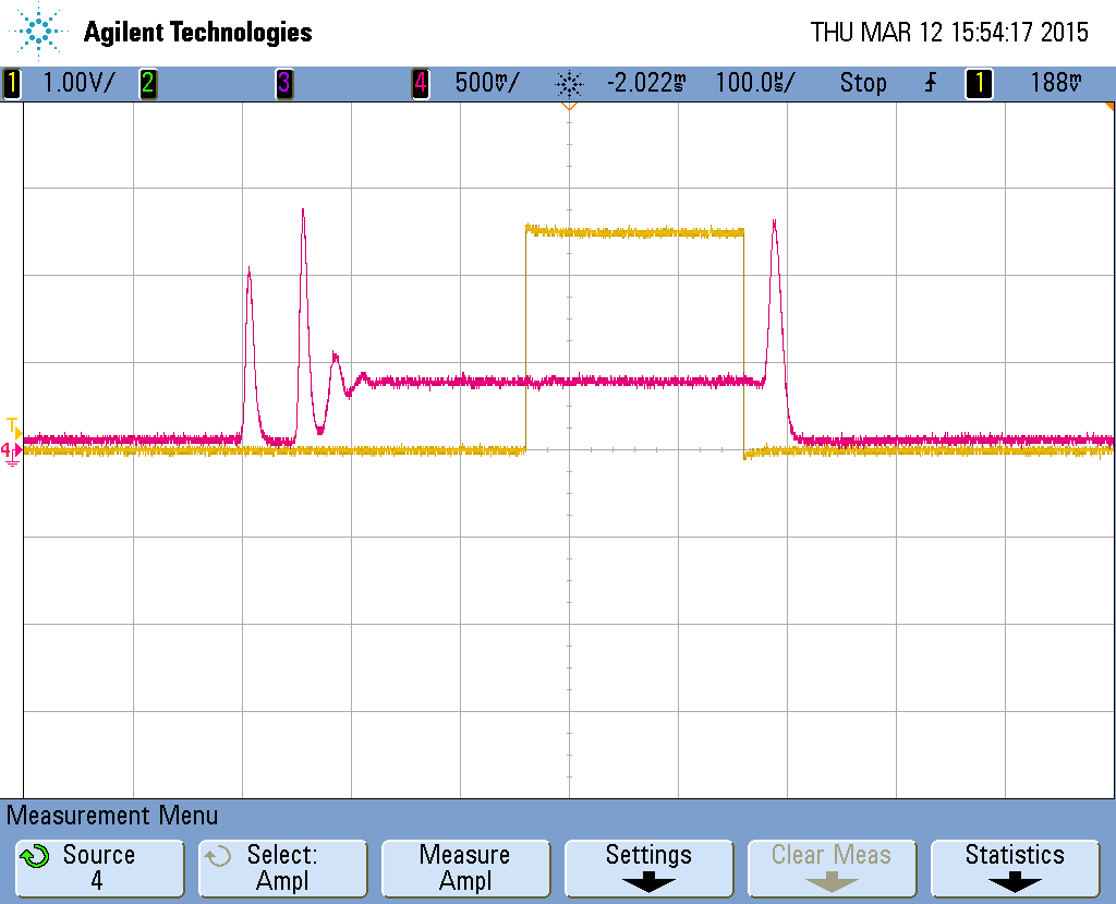
I get about 1.5ms power down time at 2ms sleep time in both power modes. The power-up time is about 250us for both power modes in my application.

Does anyone else have any experience on this subject?

Or maybe there is a timing graph for the power mode floating around somewhere and I haven't found it? 

  • Hi,

    Your query had been forwarded to a hardware expert, which will respond soon.

    Best regards,

    OD

  • Hi Lars,

    can you elaborate on how you are measuring the times?

    Thanks...

  • Hi,

    I am measuring the times between AD-conversions with a MAX9918 Evaluation kit.

    The results are shown below. Do not pay much attention to the current values as they are affected by constant circuitry current consumtion as well. 

    You can see that the power down time after each AD-conversion is very much the same for PM1 and PM2. (about 1.5ms).

    The green line is the current, while the pink(-ish) line is the AD-conversion.

    I run a AD-Conversion every 2ms.

    PM1


    PM2:

  • Hi Lars,

    I did some measurements with PM1 and PM2 modes. Results are shown below. The measured currents in PM1 = 0.230mA and PM2 = 1.2uA.

    I have setup the sleep timer to generate interrupts every 1sec after which it enters an ISR. The ISR turns on an LED immediately (blue trace) and right after exiting the ISR and before entering the power modes, the LED is shut down.

    The yellow trace is the voltage profile across a small resistor in series with the power supply to the chip. The transitions on the blue trace show states of LED.

    You can see that the the wake-up time from PM1 is smaller than the wake-up time from PM2. However, the sleep times are similar.

    PM1

    PM2


  • Hi,

    This is a good start, but my issue was the power-down time at sleep times below 3ms. 

    Can you redo this test with a sleep time of 2ms, and look at the power-down time?

    The power down-time look quite similar in your test, just like mine.

    (That is, the time from when your LED turns off, to the point where you have your lowest current consumption).

    The CC2530 users guide clearly states:

    "PM1 is used when the expected time until a wakeup event is relatively short (less than 3 ms), because
    PM1 uses a fast power-down and power-up sequence." (ref. 4.1.2 page 62).

  • Hi Lars,
    Can you try doing the test with system running on RCOSC instead of the XTAL? This way active to PM1 time is around 20uSec and active to PM2 time is around 30uSec.
  • Hi again,

    This seems to be correct. I get about 50us power down time, though.

    This is an explanation, but not a good solution for me, as I need to keep the 32MHz XTAL up and running as I plan to use the radio at certain points in my code.

    I really think these parameters should be given in the data sheet as it is relevant to know, in a SoC Radio were it is need for a 32MHz XTAL to run the radio, that there is a difference in power down time for the power modes for different oscillators. 

    This is my last measurement. PM2-->Port set for 200us-->PM2

    Yellow= port signal

    Pink= current draw