This thread has been locked.

If you have a related question, please click the "Ask a related question" button in the top right corner. The newly created question will be automatically linked to this question.

CC2538 program through Bootloader

Other Parts Discussed in Thread: CC2538

Hello All,

Our customer have following doubt in CC2538.

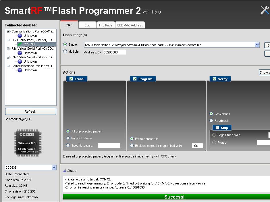
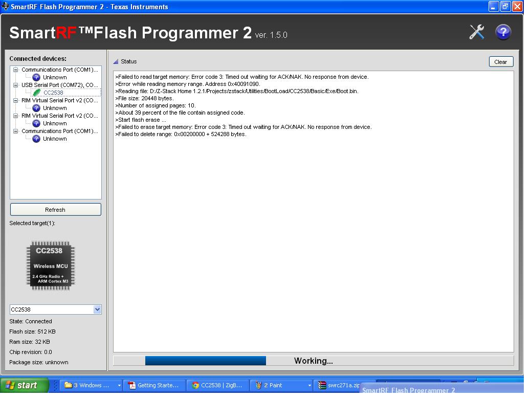
For the RF board with cc2538 we are using UART0 to program through Bootloader. (Pin PA7 is Active High) but we are not able to program it.

The Tool we are using for programming is SerialBootTool and the error shown is "Response Time Out".

Also kindly inform us how to access CCA (Customer Configuration Area)?

Kindly let us know if any more information is needed on the same.

Awaiting for your valuable response.

  • Can you try using the SmartRF programmer 2 (www.ti.com/.../flash-programmer) to program the device. More information on an SBL example and CCA can be found here: www.ti.com/.../swra466.pdf

    Regards,
    TC.
  • Hello TC,

    We have already tried:
    1). SmartRF programmer, but the device (MCU) is not getting detected, tool says "Failed to read Target Memory, Error Code 3, timeout waiting for ACK/ NACK" So how is the device suppose to send the ACK/ NACk? Is it through the Custom Serial Protocol on UART0 port.
    If so, then how and where to implement the protocol?

    Please find the updated details for error shown while trying to

    (A) "connect" the cc2538 chip to smart Rf programmer 2:

    (B) While programming cc2538:


    2). CCA address is mentioned in SWRA466 document and resides in flash (@ address 2007), but since we are not able to program the MCU we cannot write in CCA?

    3). Also tried to program through IAR JTAG programmer (JLINK), but no response from MCU.

    Kindly note the following points:
    1). We are using USB to TTL converter to program from UART0 Pins (Tool is Serial boot tool/ Smart RF programmer 2).

    2). Hardware connection's at Port A, Pin PA7 is Pulled up, PA0 & PA1 are connected to TX/ RX of USB to TTL converter, rest Pins for Port A are NC.


    Thanks,
    Riki Patel

  • I saw the same issue with a previous version of SmartRF Programmer. When I updated to version 1.6.0 (www.ti.com/.../flash-programmer) I was able to connect and erase the devices flash with no errors. Please update to version 1.6.0 of SmartRF studio 2 and let me know if it is still failing.

    Regards,
    TC.