Other Parts Discussed in Thread: CC2538
Hello,
I want to use CC2538 to collect my sensor data and then send the data to PC through USB CDC interface.
The connection method between CC2538 and my sensor is SPI, so I combined the SPI example code and USB_CDC code together for data transmission.
Question:
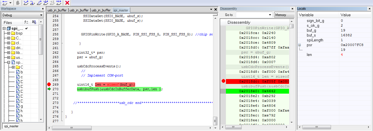
Why the parameter "count" is 0 when I debug the program? The program will stop executing "usbibufPush" if count =0.
// Include driver libraries

// Application entry point
//


//*****************************************************************************
//ssi driver library
#include <stdbool.h>
#include <stdint.h>
#include "hw_memmap.h"
#include "hw_ioc.h"
#include "gpio.h"
#include "ioc.h"
#include "ssi.h"
#include "uart.h"
#include "sys_ctrl.h"
#include "uartstdio.h"
#include "sensor.h"
#include "stdio.h"

//usb_cdc driver library
#include "bsp.h"
#include "string.h"
#include "usb_firmware_library_headers.h"
#include "usb_cdc.h"
#include "usb_in_buffer.h"
#include "usb_out_buffer.h"

//local variable for usb_cdc
USB_EPIN_RINGBUFFER_DATA usbCdcInBufferData;
USB_EPOUT_RINGBUFFER_DATA usbCdcOutBufferData;
static uint8_t pInBuffer[128];
static uint8_t pOutBuffer[128];
//
// Implementations of function that are required by usb framework.
//
//*****************************************************************************
void usbsuspHookEnteringSuspend(bool remoteWakeupAllowed)
{
    if (remoteWakeupAllowed)
    {
    }
}
void usbsuspHookExitingSuspend(void) {
}


//*******************************Sensor1*********************************//
#define PIN_SSI_CLK             GPIO_PIN_2   // Clock signal
#define PIN_SSI_FSS             GPIO_PIN_3   // Chip select--Accelerometer
#define PIN_SSI_RX              GPIO_PIN_4   // PIN_SSI_RX----MISO
#define PIN_SSI_TX              GPIO_PIN_5   // PIN_SSI_RX----MOSI
#define PIN_SSI_FSS_G           GPIO_PIN_6   // Chip select---Gyroscope
#define GPIO_SSI_BASE           GPIO_A_BASE


//*****************************************************************************

// This function sets up UART0 to be used for a console to display information
// as the example is running.

//*****************************************************************************
//*****************************************************************************
int
main(void)
{
   int sign_bit_g;
   int s_ok_g;
   uint32_t buf_g ;     // gyro_1 data
   uint32_t buf_s ;     // gyro_1 status
   //****************************ssi******************************************
    //Set the Clocking to run directly from the external crystal/oscillator
    //
    SysCtrlClockSet (false, false, SYS_CTRL_SYSDIV_32MHZ);
    //
    //Set IO Clock to the same as ststem clock(that is the Baud Rate Clock for SSI and UART)

    SysCtrlIOClockSet(SYS_CTRL_SYSDIV_32MHZ);

    //
    // Enable the SSI Peripherals
    //
    SysCtrlPeripheralEnable(SYS_CTRL_PERIPH_SSI0);

    //
    // Disable SSI function before configuring module
    //
    SSIDisable(SSI0_BASE);

    //
    //Set IO clock as SSI clock source
    //
    SSIClockSourceSet(SSI0_BASE, SSI_CLOCK_PIOSC);

    //
    //Configure the pin muxing for SSI0 functions on port A2, A3, A4 and A5
    //

    //*******************************Sensor1*********************************//
    IOCPinConfigPeriphOutput(GPIO_SSI_BASE, PIN_SSI_CLK,
                             IOC_MUX_OUT_SEL_SSI0_CLKOUT);

    IOCPinConfigPeriphOutput(GPIO_SSI_BASE, PIN_SSI_FSS,
                             IOC_MUX_OUT_SEL_SSI0_FSSOUT);

    IOCPinConfigPeriphOutput(GPIO_SSI_BASE, PIN_SSI_FSS_G,
                             IOC_MUX_OUT_SEL_SSI0_FSSOUT);

    IOCPinConfigPeriphOutput(GPIO_SSI_BASE, PIN_SSI_TX,
                             IOC_MUX_OUT_SEL_SSI0_TXD);

    IOCPinConfigPeriphInput(GPIO_SSI_BASE, PIN_SSI_RX,
                            IOC_SSIRXD_SSI0);


    //*******************************Sensor1*********************************//
    GPIOPinTypeGPIOOutput(GPIO_A_BASE, PIN_SSI_FSS);
    GPIOPinTypeGPIOOutput(GPIO_A_BASE, PIN_SSI_FSS_G);
    GPIOPinWrite(GPIO_A_BASE, PIN_SSI_FSS_G, PIN_SSI_FSS_G);
    GPIOPinWrite(GPIO_A_BASE, PIN_SSI_FSS, PIN_SSI_FSS);
    GPIOPinTypeSSI(GPIO_SSI_BASE, PIN_SSI_CLK |PIN_SSI_RX |PIN_SSI_TX);


    //
    // Configure SSI module to Motorola/Freescale SPI mode 0:
    // Polarity  = 0, Phase     = 0
    // Word size = 16 bits
    //
    SSIConfigSetExpClk(SSI0_BASE, SysCtrlIOClockGet(), SSI_FRF_MOTO_MODE_0,
                       SSI_MODE_MASTER,115200, 16);

    //
    // Enable the SSI0 module.
    //
    SSIEnable(SSI0_BASE);


  //*******************************Sensor1_Status*****************************//
      GPIOPinWrite(GPIO_A_BASE, PIN_SSI_FSS_G, 0x0000); //chip select--low
      SSIDataPut (SSI0_BASE, 0x0040 );                  // Read status register first time
      SSIDataPut (SSI0_BASE, 0x0040 );
      while(SSIBusy(SSI0_BASE))
         {
         }
     SSIDataGet(SSI0_BASE, &buf_s);
     SSIDataGet(SSI0_BASE, &buf_s);

     SSIDataPut (SSI0_BASE, 0x0040 );                  // Read status register second time
     SSIDataPut (SSI0_BASE, 0x0040 );
      while(SSIBusy(SSI0_BASE))
         {
         }
     SSIDataGet(SSI0_BASE, &buf_s);
     SSIDataGet(SSI0_BASE, &buf_s);
     GPIOPinWrite(GPIO_A_BASE, PIN_SSI_FSS_G, PIN_SSI_FSS_G);
     //******************usb_cdc**************************************************
  //
    // Initialize board and system clock
    //
    bspInit(SYS_CTRL_32MHZ);

    //
    // Initialize buffers
    //
    memset(&usbCdcInBufferData, 0x00, sizeof(USB_EPIN_RINGBUFFER_DATA));
    usbCdcInBufferData.pBuffer = pInBuffer;
    usbCdcInBufferData.size = sizeof(pInBuffer);
    usbCdcInBufferData.endpointReg = USB_F4;
    usbCdcInBufferData.endpointIndex = 4;
    usbCdcInBufferData.endpointSize = 64;
    memset(&usbCdcOutBufferData, 0x00, sizeof(USB_EPOUT_RINGBUFFER_DATA));
    usbCdcOutBufferData.pBuffer = pOutBuffer;
    usbCdcOutBufferData.size = sizeof(pOutBuffer);
    usbCdcOutBufferData.endpointReg = USB_F4;
    usbCdcOutBufferData.endpointIndex = 4;


    uint16_t spiLength = 1;


    //
    // Enable the USB interface
    //
    usbCdcInit(115200);    //void usbCdcInit(uint32_t baudrate);

    //
    // Main loop
    //

    while (1)
    {
        //
        // Process USB events

           if (buf_s)
     {
             // Process USB events

    //*********************Sensor_1 Gyro***********************//
        GPIOPinWrite(GPIO_A_BASE, PIN_SSI_FSS_G, 0x0000); //chip select--low
        SSIDataPut (SSI0_BASE, 0x0001 );
        SSIDataPut (SSI0_BASE, 0x0001 );  // Read Rate_[X] register
         while(SSIBusy(SSI0_BASE))
         {
         }

        SSIDataGet(SSI0_BASE, &buf_s);
        SSIDataGet(SSI0_BASE, &buf_g);    // read data from Rx FIFO
        s_ok_g = buf_g & (1 << 1);     //Gyro_1 ok status bit
        sign_bit_g = buf_g & 0xf000;

        if (sign_bit_g==0)
        {
          buf_g &= 0xfff;

        }
          //**************usb_cdc end***************

        else
        {

        // Implement COM-port loopback

          buf_g &= 0xfff;
          buf_g ^= 0xfff;
          buf_g = buf_g + 1;
          buf_g = 0- buf_g;

        }

        GPIOPinWrite(GPIO_A_BASE, PIN_SSI_FSS_G, PIN_SSI_FSS_G); //chip select--high

     }
//***************************************************************************//
//If Gyro status is not 1, read gyro status register again, till gyro status is ok.
  else
   {
         //UARTprintf("Gyro s_ok fail: s_ok = %d, need to reset the system\n", s_ok_s);

          GPIOPinWrite(GPIO_A_BASE, PIN_SSI_FSS_G, 0x0000); //chip select--low

          SSIDataPut (SSI0_BASE, 0x0040 );                  // Read status register first time
          SSIDataPut (SSI0_BASE, 0x0040 );
          while(SSIBusy(SSI0_BASE))
            {
            }
         SSIDataGet(SSI0_BASE, &buf_s);
         SSIDataGet(SSI0_BASE, &buf_s);


        GPIOPinWrite(GPIO_A_BASE, PIN_SSI_FSS_G, PIN_SSI_FSS_G); //chip select--high

       }

      uint32_t* psr;
      psr = &buf_g;

        //
      usbCdcProcessEvents();
        //
        // Implement COM-port loopback
        //
      uint16_t count = usbibufGetMaxPushCount(&usbCdcInBufferData);
      uint16_t maxPopCount = usbobufGetMaxPopCount(&usbCdcOutBufferData);

      if (count > maxPopCount)
      {
        count = maxPopCount;
      }
      if (count)
      {
        // usbobufPop(&usbCdcOutBufferData, pAppBuffer, count);
        //
        // send the string sensor data to console
        //
        usbibufPush(&usbCdcInBufferData, psr, spiLength);
      }
    }

    //*********************usb_cdc end*****************************************

   }