This thread has been locked.

If you have a related question, please click the "Ask a related question" button in the top right corner. The newly created question will be automatically linked to this question.

Getting Started with 2650

Other Parts Discussed in Thread: CC2650, Z-STACK, IAR-KICKSTART, CC2530EM

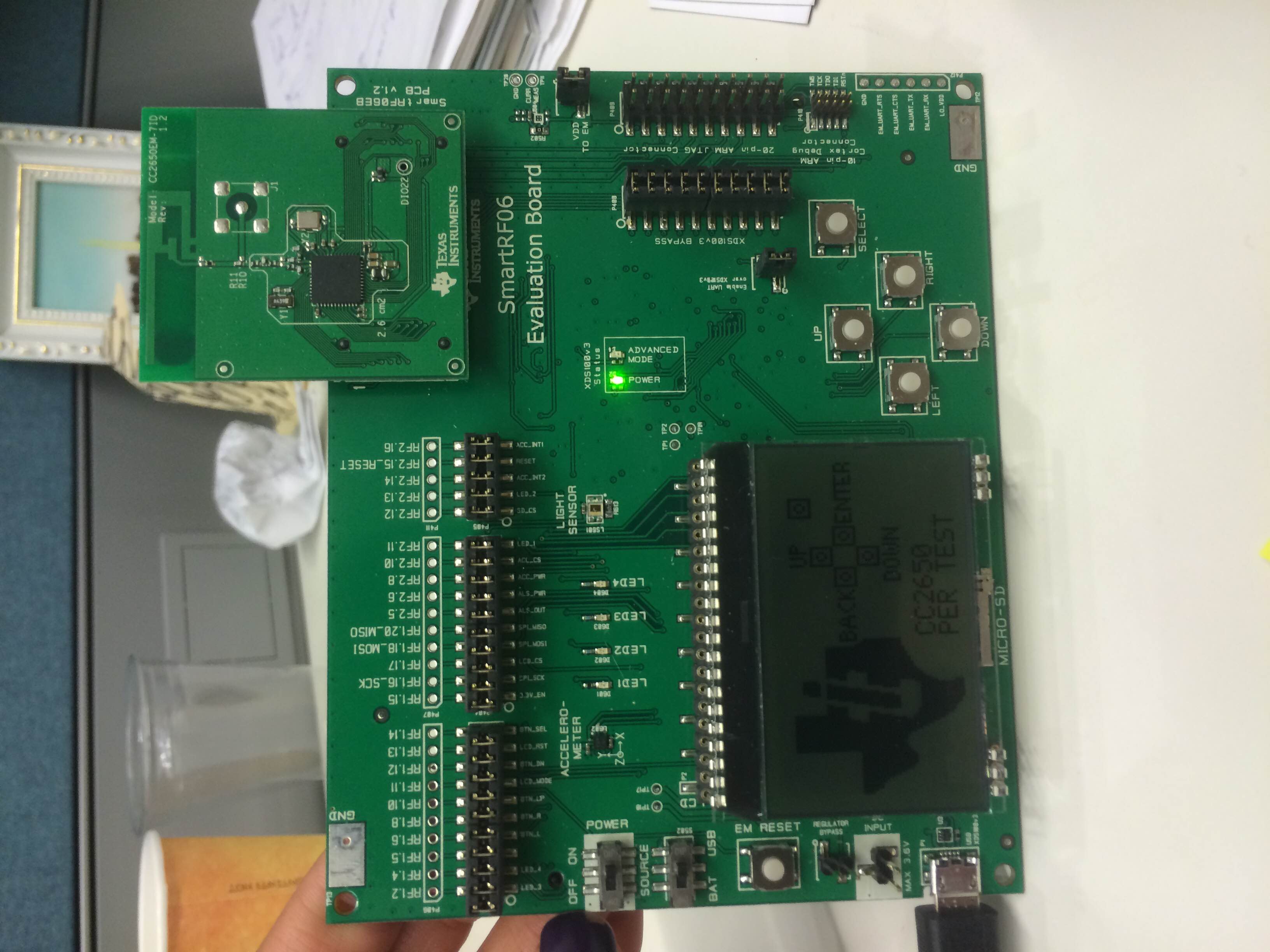
I am the most beginner of beginners with microcontrollers in general, but am attempting at familiarizing myself with the CC2650 from a ZigBee standpoint. My goal is just to get a "Hello World" to show up on the display. I am currently downloading CCS to program the board, but I was wondering what my step is after this. Do I have to configure the board (it's a CC2650 Evaluation Module with the RF06 Evaluation Board) with the software? I'm hoping for a step by step process as far as what to do, how to set up a project etc after I install CCS. Is there any other required software?

  • You have to use IAR for ARM to build Z-Stack Home 1.2.2 examples for CC2650. Z-Stack examples cannot be built by CCS.
  • So what do I do once I've installed IAR?
  • You can download and install Z-Stack Home 1.2.2. You can start from studying SampleSwitch example in Z-Stack home 1.2.2. There are documents in it and you should read them first.
  • I'm looking through the documents and it seems that they all have to do with the 2530 or 2538. I'm using the 2650, is there supporting documentation for this?
  • Also, there are 2 IAR kickstarts to download from TI: the IAR-KICKSTART for MSP430 and the IAR-KICKSTART-MSP432. Which one do I need?
  • You should download IAR for ARM V7.40.2 from www.iar.com/.../ti-wireless
  • Hi Ena,

    Go to ~\ti\simplelink\zstack_home_1_02_02_42930\Documents, and open Z-Stack Home Sample Application User's Guide. This document provides helpful instructions for loading and running the examples using IAR. Section 3.1.2 focuses on loading and running CC2650 sample applications.

    Rex
  • You should read Z-Stack Home Sample Application User's Guide.pdf under C:\ti\simplelink\zstack_home_1_02_02_42930\Documents. The examples for CC2650 are under C:\ti\simplelink\zstack_home_1_02_02_42930\Projects\zstack\HomeAutomation.
  • Hi Rex,

    So I've been trying to get this working, but I'm definitely stuck from the very beginning. I'm looking at page 20 of the Sample Application User's Guide. I am looking under sectoin 3.1.2, and I connected the SmartRF06 EB and CC2650EM via USB to my laptop, and powered them on, and nothing happens in IAR. Under the third step of this section, it says to erase memory but there is nothing to erase. There is no evidence that IAR Embedded Workbench even recognizes that the board has been connected to the laptop. If I look under the next step, step 4, I have to select an active project. But there are no projects for me to select from. I am literally starting from a blank slate in IAR, and am wondering what the intermediate steps there are missing from the user guide that link what happens between when you download IAR and when you plug in your board.
  • Hi Ena,

    After downloading IAR, you have to select a project to open.
    1. Go to File --> Open --> Workspace...
    2. Navigate to ~\ti\simplelink\zstack_home_1_02_02_42930\Projects\zstack\HomeAutomation
    3. Select a project, and find a file with a *.eww file extension.
    4. If you want to load SampleSwitch, go to ~\ti\simplelink\zstack_home_1_02_02_42930\Projects\zstack\HomeAutomation\SampleSwitch\CC26xx
    and open SampleSwitch.eww

    In the HomeAutomation folder, there are several projects that are described in the Sample Application User's Guide.

    Rex
  • Rex,

    So I followed you to this directory and there was no SampleSwitch.eww, there was an ICF file, ICallADDrs.h, main.c, startup_iar.c, switch.c, switch.h, znwk_config.h, and start_config.h. So I created a new project and uploaded all of these files into it. Then I wanted to see just if one of the source files would compile and I'm getting an error about xdc/std.h and how it can't be found. Did I forget to upload something else?

    Also, I'm still failing to see how IAR knows to communicate with my evaluation board...isn't there some kind of other set up I need? I really just want to be able to send Hello World to the LCD right now.

    Lastly, if I did get the Sample Switch to work, how would I know? Is there a way to attach the ZLight2 to the evaluation board or module that I could test the turning on and off function with?
  • Ena,

    If you see all those files in the directory that I listed, you should be able to see "SampleSwitch.eww". If not, you might need to reinstall Z-Stack Home Automation.

    Installing Z-stack should automatically install the driver needed. The sample application already has all the driver configuration setup so if you can open "SampleSwitch.eww", then you will be able to compile and flash your device.

    If SampleSwitch successfully compiles and loads onto your device, Section 3.2.1 of the Z-Stack Home Sample Application User's Guide has a description of what you should see, and some brief instructions to help you get started.
  • Rex,

    Thanks so much, I redownloaded and things were running smoothly until I got to step number 7 under 3.1.2. Upon pressing the Download and Debug button, this error popped up:
    "The debugging session could not be started.
    Either the debugger initialization failed, or else the file "C:\ti\simplelink\zstack_home_1_02_02_42930\Projects\zstack\HomeAutomation\SampleSwitch\CC26xx\..\..\..\..\..\Projects\zstack\Core\Thread\CC26xx\EndDevice\Exe\ZStackCoreEndDevice.out" was corrupt or of an unsupported format.
    There might be more information in the Debug Log window."
    What does this mean? Should I try re-downloading everything again?

    Thank you!
  • False alarm, I figured it out!
  • Rex,

    So I finished up section 3.1, and am now going to section 3.2. All I have in my possession are 2 SmartRF06 Evaluation boards, 2 CC2650 Evaluation Modules, and 3 Zlight2 boards with their remote control. To continue in section 3.2, it says to power on my sample light and sample switch board. Does that mean to say that I need another board?

    Thanks,

    Ena

  • When CC26xx is used as SOC mode, it can only act as Zigbee end device. To form a Zigbee network, you will need a Zigbee coordinator, which only CC253x can do. However, you can use ZAP+ZNP mode for CC2650 to act as Zigbee coordinator. You can refer to Z-Stack ZNP Interface Specification.pdf under C:\ti\simplelink\zstack_home_1_02_02_42930\Documents\API folder.
  • Ok. So I'm getting this correct, ZAP+ZNP mode is something I can kind of just turn on on the CC2650 (by coding it) to allow it to act as a coordinator? Is there existing code for that already?
    Also, can I just confirm this with you? I have to Evaluation Modules and boards. Let's say I connect Evaluation Board #1 to my laptop for power and to be programmed, and I power up Evaluation Board 2 via a USB power source, but it is NOT connected to my laptop at all. Is it possible for me to hook up Evaluation Board #1 to my laptop, and program it so that when I press the Up button (SW1) on the first evaluation board , then LED1 on Evaluation Board 2 will light up?
  • ZAP (ZigBee Application Processor) + ZNP (ZigBee Network Processor) means, you program the CC2650 with, say, Coordinator-Firmware (see \simplelink\zstack_home_1_02_02_42930\Projects\zstack\ZAP\ZNP-HexFiles\CC26xx) using the SmartRF Flash Programmer 2 and connect a Host-Microcontroller like a MSP430 to it or you connect it to your PC and interact with it, using the Z-Tool 2.


    hypothetically, yes what you wanna do is possible.
    I've already done something similar by modifying the Z-Stack source code, so i could do this without needing a ZAP, but it's been a lot of try and error. What i did is set up a Coordinator that starts up once it's powered (usually it's in hold-state till you send a startup-command) and then start sendig packets to its PAN. I set up the other 2250module as router which flashes a LED every time a packet is received.

    I haven't tried using buttons so far.

  • Do you have to do the set up this way? Because I know that without any coding, I can already get one board to send packets to the other board...
  • If you already can get one board to send packets to the other board, why cannot you just turn on LED when the packet is received. Doesn't this serve your purpose?
  • YK,

    I don't know how to do that; where in the source code would I do that? The only reason I could get the boards to communicate that way was because that was the default setting, no programming required. I want to be able to make the LED turn on whenever I want, with the press of a button.
    Thank you!
  • I see. You use default PER test to do TX and RX test. There is no source code available for CC2650 PER test so Stephanie's suggestion is necessary to do to serve your purpose. By the way, if you have CC2530DK, it will be easier. Because, you can config SmartRF05EB+CC2530EM as Zigbee SampleLight coordinator and SmarRF06EB+CC250EM as Zigbee SampleSwitch end device. Let SampleSwitch joins SampleLight network and do binding. THen,you can control LED on SampleLight from SampleSwitch.
  • I think you forgot a number...which do I use as the SampleSwitch end device? The SmartRF06+CC2560EM? Also, so I need the CC2530DK? Is it not possible to do this with the two boards I have right now?
  • You should set SmartRF06+CC2560EM as SampleSwitch end device. If you have CC2530DK, it would make you easier to test this. As I told you, CC2650 cannot act as coordinator and router if you use it as SOC mode.
  • Hi,

    Your best option is to configure one CC2650 + smartrf06 as a ZNP coordinator, a CC2650 + smartrf06 as a sample switch and also use a ZLight.

    Probably the most difficult part of doing this might be setting up the ZNP since you are new to using our devices.

    To set up the CC2650 ZNP Coordinator:

    - Using Flash Programmer 2 flash the CC2650 with the hex file provided in

    "C:\ti\simplelink\zstack_home_1_02_02_42930\Projects\zstack\ZAP\ZNP-HexFiles\CC26xx\znp_coordinator_pro_secure_linkkeyjoin.hex"

    - After flashing the board, open Z-Tool and make sure your SmartRF06 +CC2650 ZNP is plugged in your PC using the USB cable.

    - Make sure you know what "COM" port is assigned to the SmartRF06 board.

    - On Z-Tool go to the menu  Tools -> Settings and click on the Serial Devices tab.

    -  Select the COM port assigned to your SmartRF06 and click the Edit button.

    - Now select the Rate to be 115200 and click OK.

    - Now go to the menu Tools - Scan for Devices

    - If this is successful you will see a new window showing the COM port where the ZNP is connected to.

    - Now go to Tools -> Script Window

    - On the script window click on File -> Load and open the following script:
     " C:\ti\simplelink\zstack_home_1_02_02_42930\Tools\Z-Tool\Scripts\znp-bringup.zjs "

    -  On the left panel of the script window right click on znp-bringup.zjs and select edit script.

    - This will open a text editor to edit the script.

    - Now follow the instructions provided in the script.

    - This script is set up to channel 19 so you might want to switch it to be in channel 11 to do this just replace line # 174 with the following line of code:

    cfgArr[0] = 0x00; cfgArr[1] = 0x08; cfgArr[2] = 0x00; cfgArr[3] = 0x00;

    - After following the instructions in the script and running the script, close the script window.

    - Now your ZNP should be successfully set up as a coordinator

    Now you can pair the sample switch and ZLight to the ZNP Coordinator.

    After this you should be able to send commands between any devices that join the coordinator.

    Regards,

    Hector

  • Hector,

    I attempted to use the flash the board, but it keeps failing. This is the screen I am getting:

    Do I have to put the device in bootloader mode? What does that mean?

    Thanks so much!

  • You should be using the XDS100v3 to flash the board instead of the USB Serial Port because otherwise you need to make the board go into boorloader mode.

    click the refresh button and under XDS100v3, XDS-06EB12202... it should say CC2650 instead of unknown if that doesnt happen make sure the CC2650EM is properly mounted on the SmartRF06.

    If this for some reason doesnt work then try doing a flash erase using IAR and try to flash the board again with Flash programmer 2

  • Hector,

    Thanks so much! So now that I have one of my boards programmed as a coordinator, I can use either my other board, or a Zlight 2 as an end device? And how do I program that? In IAR?
  • Also, is there a way to confirm that this device is the coordinator?
  • For the Zlight it might have already something flashed if not you will have to use IAR and a CC debuger and for the CC2650 you will have to use IAR and the SmartRF06 board.

    One way that you can do to confirm that it is a coordinator is using a sniffer to see the messages over the air.
  • So I haven't done anything different from before, but I decided to try and start all over, because I thought I'd try something different. I uninstalled/ deleted all the TI folders and everything that had to do with the Z-Stack and Home automation etc. After re-downloading, I tried following the instructions on the home sample application user's guide. When I do step one, however, in an attempt to erase the memory, I get this error. I then decided to try and skip this step, but not matter what I do, on both boards, this error message comes up. I haven't done anything different from before, so I am really confused on what's going on.

  • If you use Flash Programmer 2, can you download any hex file under C:\ti\simplelink\zstack_home_1_02_02_42930\Projects\zstack\ZAP\ZNP-HexFiles\CC26xx to your CC2650DK?
  • No. Flash Programmer isn't working either
  • Can you attach a screen shot of your Flash Programmer 2?
  • In this instance, it isn't even recognizing the device. This happens about 80% of the time I plug the board in, and I usually try mass erase, which works sometimes but not this time. I tried loading a hex file into my other board etc and this happens, but then when I do the erase it works. It's just this board...

  • This looks your SmarRF06EB works fine. Can you take a picture on how you connect your CC2650EM and SmarRF06EB?
  • I know that the CC2650 is connected alright because the default screen shows

  • Yes, both your CC2650EM and SmarRF06EB look fine. This is really strange. I suggest you call TI local representative to help you.
  • Thank you so much. I have a quick question assuming that all of this works again. So, before I flashed one of my boards to act as the coordinator. In the home sample application user guide, I used steps 1-5 for the end device, do I then continue with steps 6-8 for the coordinator? Like I switch boards after step 5?
  • CC2650 cannot be configured to coordinator in SOC mode. If you want to make it act as coordinator, you have to use extra CPU/MCU to act as ZAP+ZNP mode.
  • Hector,

    So now that I've flashed the board, I don't program that board to be an end device anymore, correct? As in, I don't download active application for the End Device mode in IAR?

    So my goal now is to press SW1 (The up button) on one SmartRF06/ CC2650, and have LED1 on the other SmartRF06/ CC2650 light up whenever this button is pressed. Is this possible? Because I'm getting mixed reviews on that.

    Thanks!
  • If you want to do "press SW1 (The up button) on one SmartRF06/ CC2650, and have LED1 on the other SmartRF06/ CC2650 light up ", you can config one SmartRF06/ CC2650 as Soc which acts as SampleSwich and another SmartRF06/ CC2650 as ZAP+ZNP which acts as SampleLight. For SampleSwich, you can just build and download it from Z-Stack Home 1.2.2 examples. As for SampleLight, you can download prebuild ZNP image znp_coordinator_pro_secure_linkkeyjoin.hex in C:\ti\simplelink\zstack_home_1_02_02_42930\Projects\zstack\ZAP\ZNP-HexFiles\CC26xx and run znp-bringup.zjs in ZTool to make another SmartRF06/ CC2650 to act as SampleLight. However, it is not easy to make it for a Z-Stack newbie to do this. If it is possible, I would suggest you to buy CC2530DK or CC2538DK to act as SampleLight coordinator.
  • I have a new question about addressing. I'm assuming each board has its own address, and they know the addresses of their corresponding receiver/ transmitter; that's how they communicate. So how do I know what their addresses are? For example, right now the transmitter knows to send data to the receiver board with address x. Now, I want it to use a different receiver board, but either a) assign the new receiver with the same address x, or b) code the transmitter to send data to the new receiver board with address y.

    How do I know what the addresses are of each board? 

  • In Zigbee, we use binding to know the destination address to send message.
  • I'm looking from a software point of view. I understand what you're saying, but for point to point communication etc, there has to be a way that we know the addresses or our chips, correct? How do I know what their addresses are?
  • If you mean to know short address of device in Zigbee network, you can use API NLME_GetShortAddr to get it.
  • How do you return the CC2650 to their factory settings with the default PER test?
  • You can download PER test hex file from e2e.ti.com/.../1526507 and use Flash Programmer 2 to download the hex file into your CC2650DK.
  • Hi Yikai Chen,

    I am beginner for the Zigbee and I am trying to learn Zigbee HA with CC2650. I would like to establish communication between two CC2650

    I have followed above mentioned procedure to make

     - One CC2650 as End Device

    - Other CC2650 as ZC (ZNP + ZAP with the help of Ztool)

    I need clarifications on below :

    - LCD display is turned ON only in Zigbee End device but in ZC(Ztool+ZNP) LCD monitor is blank. Is it expectable?

    - Is there any help document which explains basic steps to establish communication between two devices?