Hello!
I have quite comlicated problem which can imply several possible solutions and I'm asking for help to choose the most fastest, easiest and gracefull solution or approach.
Here I'll try to explain the problem in detail.
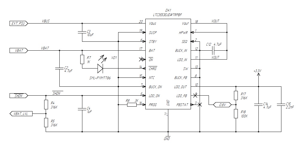
I have several (3 exactly) CC2530 based boards, powered by 1-LiPo battery and having LTC3553 chip used for charging, LDO and power control. Apparently the chip is used not as expected (i.e. push button controller is not used), but it works. The LDO_ON signal is used to switch on\off the board and the same line is connected to voltage divider, which in turn is connected to CC2530's ADC input. The difference between the boards I have that they use different ADC channels for battery voltage measument. The main problem is that the board can be turned on, but does not turn off. The root of the problem comes from that there's some voltage present on ADC input, that supplies power to LDO_ON pin therefore enabling the chip untill fully draining the battery, which is not that good.
Here on the schematics VBAT_LVL is directly connected to ADC channel 0 (or 6 on another board), ADC reference is AVDD(3.3V).
/SHDN line goes to external mechanical switch to BAT+ through USBLC6 ESD protection circuit (which I think does not affect the problem). When we switch on the board, BAT+ is connected to /SHDN and LDO is enabled. When we try to switch off the board, BAT+ is disconnected, but LDO_ON is still supplied from ADC line.
Obviously the problem can be resolved by fixing the schematics, but it should be done in software. Generally, we dont need to measure the voltage all the time. Let's say, having several measuments per minute will be enough. So, the most time instead of ADC input we can configure this pin as output and set it to zero, and occasinally reconfigure it as ADC input, make some measuments and set it back to output. Software project is quite complex and hard to support, that's why I'm asking about graceful solution.
Now it is implemeted as follows:
ADC is configured using ADC sequences of 4 channels, one of them is battery voltage (ADC0). There's an array of 12 values (3 times more than needed - I dont know why?) which is filled by DMA with ADC_CHALL trigger mode, transfer length is 12 words.
Now I'm thinking about fixing the problem excluding AIN0 from ADC sequences, then making BAT voltage measuments and then reconfiguring ADC back again.
The procedure looks like following:
- stop ADC DMA channel
- setup AIN0 as ADC (was GPIO output)
- wait for a while to charge the input (how long?)
- read AIN0 (using HalAdcRead() or whatever)
- reconfigure back AIN0 as GPIO output
- enable DMA and start ADC
Well, the problem is that the whole procedure should be as fast as possible (not to break ZStack) and/or the values at DMA destination should not be corrupted.
Sorry for such a long explanation and thanks in advance.
Andrey.