Hi
i want to design a firmware which could be achieve as smartRF studio Continue Tx function to sending the RF signal , then we could using smartRF studio could catch in Continue RX window。
( and i hope those firmware would be as a part of the lastest version and being used in Mass production。)
As testing
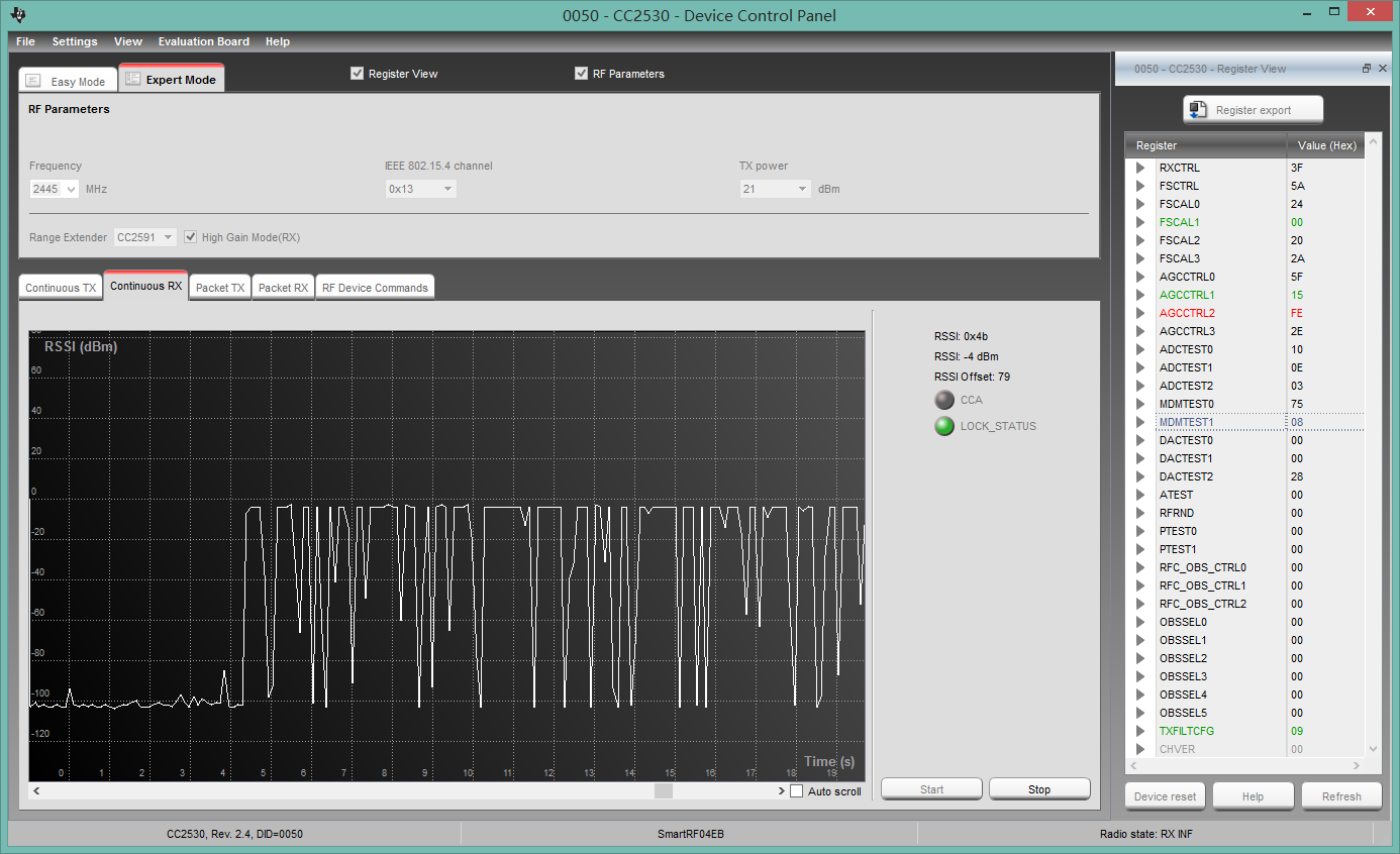
first step , i copy all the regsiter vaule in smartRF studio as below

and then i build a project , and set the regsiter vaule following upstair.
int main {
P0=0xFF ; //Port 0
P1=0xEF ; //Port 1
P0DIR=0x80 ; //Port 0 Direction
P1DIR=0x12 ; //Port 1 Direction
FRMFILT0=0x0D ; //Frame Filtering
FRMFILT1=0x78 ; //Frame Filtering
SRCMATCH=0x07 ; //Source Address Matching and Pending Bits
SRCSHORTEN0=0x00 ; //Short Address Matching
SRCSHORTEN1=0x00 ; //Short Address Matching
SRCSHORTEN2=0x00 ; //Short Address Matching
SRCEXTEN0=0x00 ; //Extended Address Matching
SRCEXTEN1=0x00 ; //Extended Address Matching
SRCEXTEN2=0x00 ; //Extended Address Matching
FRMCTRL0=0x43 ; //Frame Handling
FRMCTRL1=0x00 ; //Frame Handling
RXENABLE=0x00 ; //RX Enabling
RXMASKSET=0x00 ; //RX Enabling
RXMASKCLR=0x00 ; //RX Disabling
FREQTUNE=0x0F ; //Crystal Oscillator Frequency Tuning
FREQCTRL=0x33 ; //Controls the RF Frequency
TXPOWER=0xF5 ; //Controls the Output Power
TXCTRL=0x69 ; //Controls the TX Settings
FSMSTAT0=0x00 ; //Radio Status Register
FSMSTAT1=0x00 ; //Radio Status Register
FIFOPCTRL=0x40 ; //FIFOP Threshold
FSMCTRL=0x01 ; //FSM Options
CCACTRL0=0xF8 ; //CCA Threshold
CCACTRL1=0x1A ; //Other CCA Options
RSSI=0x80 ; //RSSI Status Register
RSSISTAT=0x00 ; //RSSI Valid Status Register
RXFIRST=0x00 ; //First Byte in RXFIFO
RXFIFOCNT=0x00 ; //Number of Bytes in RXFIFO
TXFIFOCNT=0x00 ; //Number of Bytes in TXFIFO
RXFIRST_PTR=0x00 ; //RXFIFO Pointer
RXLAST_PTR=0x00 ; //RXFIFO Pointer
RXP1_PTR=0x00 ; //RXFIFO Pointer
TXFIRST_PTR=0x00 ; //TXFIFO Pointer
TXLAST_PTR=0x00 ; //TXFIFO Pointer
RFIRQM0=0x00 ; //RF Interrupt Masks
RFIRQM1=0x00 ; //RF Interrupt Masks
RFERRM=0x00 ; //RF Error Interrupt Mask
RFRND=0x03 ; //Random Data
MDMCTRL0=0x85 ; //Controls Modem
MDMCTRL1=0x14 ; //Controls Modem
FREQEST=0x00 ; //Estimated RF Frequency Offset
RXCTRL=0x3F ; //Tune Receive Section
FSCTRL=0x5A ; //Tune Frequency Synthesizer
FSCAL0=0x24 ; //Tune Frequency Calibration
FSCAL1=0x00 ; //Tune Frequency Calibration
FSCAL2=0x20 ; //Tune Frequency Calibration
FSCAL3=0x2A ; //Tune Frequency Calibration
AGCCTRL0=0x5F ; //AGC Dynamic Range Control
AGCCTRL1=0x15 ; //AGC Reference Level
AGCCTRL2=0xFE ; //AGC Gain Override
AGCCTRL3=0x2E ; //AGC Control
ADCTEST0=0x10 ; //ADC Tuning
ADCTEST1=0x0E ; //ADC Tuning
ADCTEST2=0x03 ; //ADC Tuning
MDMTEST0=0x75 ; //Test Register for Modem
MDMTEST1=0x08 ; //Test Register for Modem
DACTEST0=0x00 ; //DAC Override Value
DACTEST1=0x00 ; //DAC Override Value
DACTEST2=0x28 ; //DAC Test Setting
ATEST=0x00 ; //Analog Test Control
PTEST0=0x00 ; //Override Power-Down Register
PTEST1=0x00 ; //Override Power-Down Register
RFC_OBS_CTRL0=0x00 ;//RF Observation Mux Control
RFC_OBS_CTRL1=0x00 ;//RF Observation Mux Control
RFC_OBS_CTRL2=0x00 ;//RF Observation Mux Control
TXFILTCFG=0x09 ; //TX Filter Configuration
OBSSEL0=0x00 ; //Observation output control register 0
OBSSEL1=0x00 ; //Observation output control register 1
OBSSEL2=0x00 ; //Observation output control register 2
OBSSEL3=0x00 ; //Observation output control register 3
OBSSEL4=0x00 ; //Observation output control register 4
OBSSEL5=0x00 ; //Observation output control register 5
CHVER=0x00 ; //Chip Version
CHIPID=0x00 ; //Chip ID
}
and i download the firmware and run it , but i could catch anything in the smartRF studio Continue RX window

why does this could not be work ?
how could i using the firmware to simulate this Sending RF signal process?
BR