This thread has been locked.

If you have a related question, please click the "Ask a related question" button in the top right corner. The newly created question will be automatically linked to this question.

CC2530 UART1 problem

Other Parts Discussed in Thread: CC2530, Z-STACK

Hi All. We use P1_6 as TX and P1_7 as RX in cc2530 custom board. I tried to debug UART funciton in the board. So I wrote such program to test it. I'm using cc2530F256 chip and my IAR version is 9.20.2. After I run the program, I got nothing in the TX pin. I don't know why.

#include "ioCC2530.h"
#include <string.h>

#define uchar unsigned char
#define uint  unsigned int


#define led1 P0_0


void delayms(uint ms);              
void ledInit();                      
void uartInit();                     
void uartSend(char *Data, int len);  


uchar RXTXflag = 1;                  
char  temp;                          
uchar datanumber = 0;                
char  Rxdata[12] = { '0','1','2','3','4','5','6','7','8','9' };                   


/***********************************

***********************************/
void delayms(uint ms)
{
  int i, j;
  for(i=ms; i>0; i--)
    for(j=1156; j>0; j--);
}

/***********************************

***********************************/
void ledInit()
{
  P0SEL &= ~0x01;  //set as general I/O
  P0DIR |= 0x01;   //set as output
  P0INP &= ~0x01;  //set pull-up pull-down mode
 
  led1 = 0;
}

/***********************************

***********************************/
void uartInit()
{

 
  CLKCONCMD &= ~0x40;      
  while(!(SLEEPSTA & 0x40));
  CLKCONCMD &= ~0x07;     
 
  SLEEPCMD  |= 0x04;       
 
 
  //
  PERCFG &= ~0x02;            //set USART1 Alt2
  P1SEL  |=  0xc0;            //P1_7、P1_6 used as UART
  P1DIR  &=  ~0x80;             //P1_7 as input and P1_6 as output
 // P2DIR  &= ~0x80;            // the frist priority is UART1
  P2SEL &= ~ 0x20;
  P2SEL |= 0x40;
 
  //
  U1CSR  |= 0x80;              //set UART mode
  U1UCR   = 0x02;
  U1GCR  |= 10;                //set BPS 38400
  U1BAUD |= 59;               //
  UTX1IF  = 0;                 //UART1 TX interrupt
  U1CSR  |= 0x40;              //enable UART1 TX
  IEN0   |= 0x88;              //Enable Interrupt
  IEN2   |= 0x08;
 
}

/***********************************

***********************************/
void uartSend(char *Data, int len)
{
  int j;
  for(j=0; j<len; j++)         //
  {
    U1DBUF = *Data++;          //
    while(UTX1IF == 0);        //
    UTX1IF = 0;                //
  }
}

/***********************************

***********************************/
void main()
{
  //
  ledInit();
  uartInit();
#if 1
 
  datanumber = 12;
 
  while (1)
  {
      U1CSR &= ~0x40;          //disable receive
      uartSend(Rxdata, datanumber); //
      RXTXflag = 1;            //
      //datanumber = 0;          //
  }
#endif
 

}

#pragma vector = URX1_VECTOR
__interrupt void UART1_ISR(void)
{
  URX1IF = 0;  
  temp = U1DBUF;
}

  • If you would use Z-Stack in the end, I would suggest you to use APIs in hal_uart.c and HAL_UART_PORT1.
  • Ok, I will try the z-stack with APIs. Should I add HAL_UART_PORT1 in the Option->C/C++ Complier->Preprocessor->Defined symbols?
  • I mean when you use API HalUARTOpen and HalUARTWrite, you use HAL_UART_PORT_1 as first parameter. For example,

    unsigned char str[]="Hello everybody";
    halUARTCfg_t uartConfig;
    uartConfig.configured = TRUE;
    uartConfig.baudRate = HAL_UART_BR_115200;
    uartConfig.flowControl = HAL_UART_FLOW_OFF;
    uartConfig.flowControlThreshold = 4;
    uartConfig.rx.maxBufSize = 128;
    uartConfig.tx.maxBufSize = 128;
    uartConfig.idleTimeout = 6;
    uartConfig.intEnable = FALSE;
    uartConfig.callBackFunc = NULL;
    HalUARTOpen(HAL_UART_PORT_1,&uartConfig);
    HalUARTWrite(HAL_UART_PORT_1, str, 15);
  • How could I set the pin I use? I'm using P1_6 and P1_7, I don't find how to define the pin I use. I only found
    /* Ports */
    #define HAL_UART_PORT_0 0x00
    #define HAL_UART_PORT_1 0x01
    #define HAL_UART_PORT_MAX 0x02
    in the file hal_uart.h.
  • When you call HalUARTOpen with HAL_UART_PORT_1, it would setup P1.6 and P1.7 for you.
  • I tried to use HAL_UART_PORT_1 in my GenericApp_Init(byte task_id) and unsigned char str[]="Hello everybody";
    GenericApp_TaskID = task_id;
    GenericApp_TransID = 0;
    GenericApp_NwkState = DEV_INIT;
    halUARTCfg_t uartConfig;

    GenericApp_DstAddr.addrMode = (afAddrMode_t)AddrNotPresent;
    GenericApp_DstAddr.endPoint = 0;
    GenericApp_DstAddr.addr.shortAddr = 0;

    GenericApp_epDesc.endPoint = GENERICAPP_ENDPOINT;
    GenericApp_epDesc.task_id = &GenericApp_TaskID;
    GenericApp_epDesc.simpleDesc = (SimpleDescriptionFormat_t *)&GenericApp_SimpleDesc;
    GenericApp_epDesc.latencyReq = noLatencyReqs;
    afRegister(&GenericApp_epDesc);

    GenericApp_Group.ID = 0x0001;
    GenericApp_Group.name[0] = 6;
    osal_memcpy(&(GenericApp_Group.name[1]),"Group1",6);

    uartConfig.configured = TRUE;
    uartConfig.baudRate = HAL_UART_BR_115200;
    uartConfig.flowControl = HAL_UART_FLOW_OFF;
    uartConfig.flowControlThreshold = 4;
    uartConfig.rx.maxBufSize = 128;
    uartConfig.tx.maxBufSize = 128;
    uartConfig.idleTimeout = 6;
    uartConfig.intEnable = FALSE;
    //uartConfig.callBackFunc = rxCB;
    uartConfig.callBackFunc = NULL;
    HalUARTOpen(HAL_UART_PORT_1,&uartConfig);
    HalUARTWrite(HAL_UART_PORT_1,str,16);
    HalUARTWrite(HAL_UART_PORT_1,str,16);
    HalUARTWrite(HAL_UART_PORT_1,str,16);

    But when I run the program , I found that str was not output . All I got in the terminal is "H▒IEEE: 00124B00019C2EF5▒▒A▒▒▒H▒ZigBee Coord Network ID: 86FB". All these stuffs comes from the funciton void nwk_Status( uint16 statusCode, uint16 statusValue ). And I still found if I did not enter ZTOOL_P1 in the Preprocessor of Option, nothing output in the terminal. That's why?
  • Try to disable ZTOOL_P1 and MT_TASK in Defined symbols.

  • I disabled ZTOOL_P1 and MT_TASK in Defined symbols.But I got such link error:
    Error[e104]: Failed to fit all segments into specified ranges. Problem discovered in segment XDATA_N. Unable to place 2 block(s) (0xc02 byte(s) total) in 0xa89 byte(s) of memory. The problem
    occurred while processing the segment placement command "-P(XDATA)XDATA_N=_XDATA_START-_XDATA_END", where at the moment of placement the available memory ranges were
    "XDATA:1477-1eff"
  • I don't think this is caused by removing those two Defined symbols. I remove it from my GenericApp example and don't see the same problem. I think you might use a large array to cause this issue.
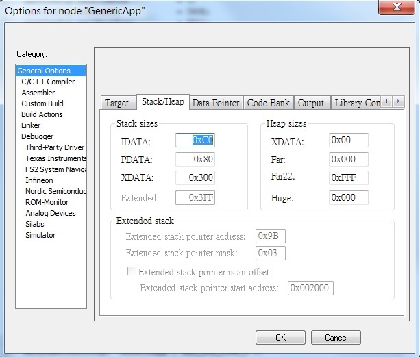
  • You are right. I changed the options--General options--Stack/Heap--XDATA value, and the link error was gone. Thank you.
    But I still not get the output in terminal. BTW, now I'm using smartRF05EB to debug the program. Now there are nothing in the terminal.
  • You have to define ZTOOL_P2 in Defined symbols.
  • Would you please to tell me the value in option->Stack/Heap. Such as Stack sizes and Heap sizes. I always get warning when I debug the program and use "Break" in Debug menu, which said "The stack point for stack'XdataStack'(currently XData:0x0000) is outside the stack range(Xdata:0x0001 to XData:0x300).
  • Thank you. Now I debug the program in smartRF05EB board. I make sure that I run the HalUARTWrite(HAL_UART_PORT1,uartbuf,16)function, but still nothing in the terminal. Now I use USB2RS232 line to connect the  RS232 interface in smartRF05EB board . Here is my defined symbols:

    xZTOOL_P1
    xMT_TASK
    ZTOOL_P2
    MT_SYS_FUNC
    MT_ZDO_FUNC
    LCD_SUPPORTED=DEBUG
    HAL_LCD=FALSE
    HAL_UART=TRUE
    HAL_DMA=TRUE

  • Try to remove the following defines.

    HAL_LCD=FALSE
    HAL_UART=TRUE
    HAL_DMA=TRUE
  • After I tried, I found only when the Defined symbols: MT_TASK, ZTOOL_P1, and HalUARTOpen(HAL_UART_PORT_0,&uartConfig);
    HalUARTWrite(HAL_UART_PORT_0,uartbuf,16); that I could get the serial output in the termainal.
    If I disable the ZTOOL_P1, only start ZTOOL_P2, and HalUARTOpen(HAL_UART_PORT_1,&uartConfig);
    HalUARTWrite(HAL_UART_PORT_1,uartbuf,16); I still could not get the output.
  • Can you show me how you connect P1.6 to your USB-to-Serial converter?
  • You are right. I implemented the UART1 output in my own board by using p1.6 and P1.7. I still have another question. "▒▒Hello everybody▒A▒" is what I got in the serail port. "Hellow everybody" is what I use HalUARTWrite to output. But other string I don't know where comes from.
  • I had tested the same HalUARTWrite with GenericApp and don't see garbage characters except "Hello everybody". Where do you put HalUARTWrite in your code?

  • void GenericApp_Init(byte task_id)
    {
    GenericApp_TaskID = task_id;
    GenericApp_TransID = 0;
    GenericApp_NwkState = DEV_INIT;
    halUARTCfg_t uartConfig;

    GenericApp_DstAddr.addrMode = (afAddrMode_t)AddrNotPresent;
    GenericApp_DstAddr.endPoint = 0;
    GenericApp_DstAddr.addr.shortAddr = 0;

    GenericApp_epDesc.endPoint = GENERICAPP_ENDPOINT;
    GenericApp_epDesc.task_id = &GenericApp_TaskID;
    GenericApp_epDesc.simpleDesc = (SimpleDescriptionFormat_t *)&GenericApp_SimpleDesc;
    GenericApp_epDesc.latencyReq = noLatencyReqs;
    afRegister(&GenericApp_epDesc);

    GenericApp_Group.ID = 0x0001;
    GenericApp_Group.name[0] = 6;
    osal_memcpy(&(GenericApp_Group.name[1]),"Group1",6);

    uartConfig.configured = TRUE;
    uartConfig.baudRate = HAL_UART_BR_115200;
    uartConfig.flowControl = HAL_UART_FLOW_OFF;
    uartConfig.flowControlThreshold = 4;
    uartConfig.rx.maxBufSize = 128;
    uartConfig.tx.maxBufSize = 128;
    uartConfig.idleTimeout = 6;
    uartConfig.intEnable = FALSE;
    //uartConfig.callBackFunc = rxCB;
    uartConfig.callBackFunc = NULL;
    HalUARTOpen(HAL_UART_PORT_1,&uartConfig);
    HalUARTWrite(HAL_UART_PORT_1,uartbuf,16);

    }
  • Try to put "HalUARTWrite(HAL_UART_PORT_1,uartbuf,16);" to your GenericApp_HandleKeys and press any button to make it do UART write. See if you still see garbage characters.
  • In our customer board, there is no key and LCD. So I just could test it in status change function.
  • Try to make a high/low change on P0.1 of your custom board which can issue a key event.
  • I tried the status change. But at the beginning there was still the strange characters. I asked the hardware engineer, he told me that maybe the ground line of serial not good.
  • If you still see this problem, I would suspect there is HW connection problem there.