This thread has been locked.

If you have a related question, please click the "Ask a related question" button in the top right corner. The newly created question will be automatically linked to this question.

Control DC motor with ZigBee

Other Parts Discussed in Thread: CC2530

Hello,

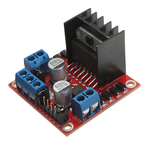
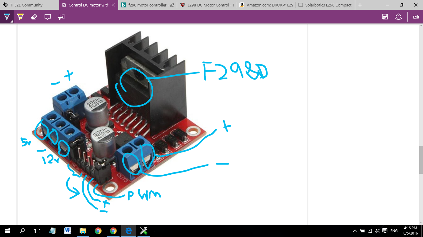
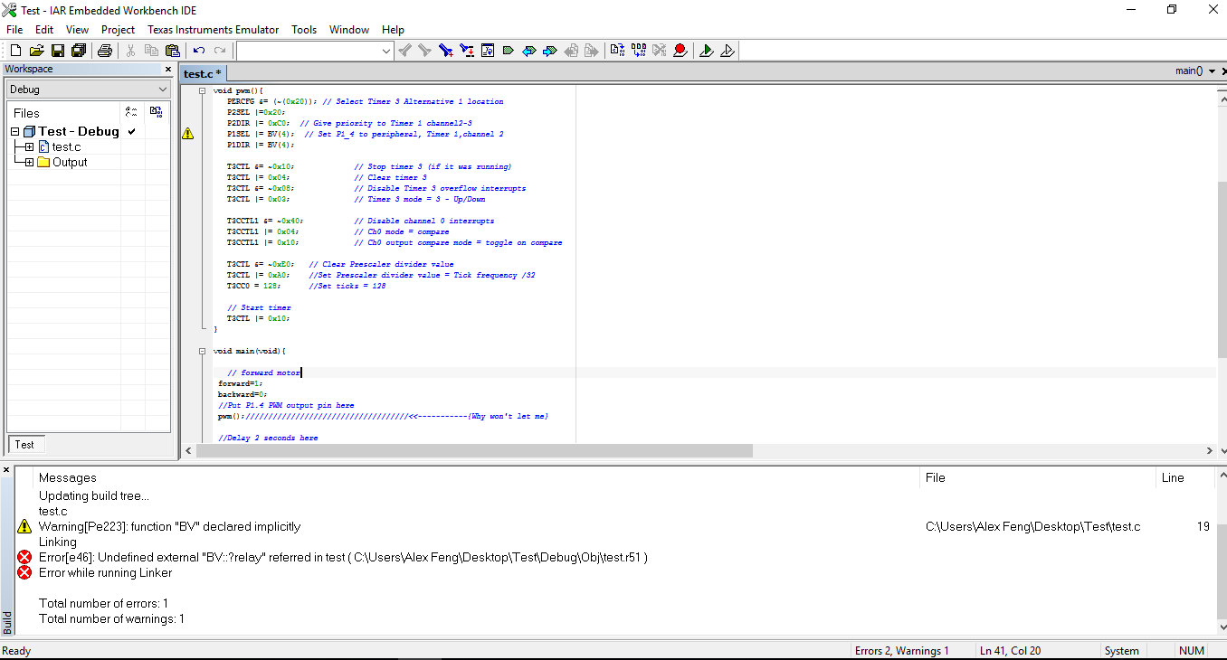
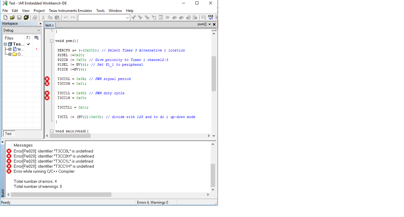
My question is how to program a ZigBee board using IAR 8051 workbench to control a DC motor to go both directions like how the automatic door lock works. The speed doesn't matter. I am seeking help from anyone as how to program a DC motor to go in 2 directions for a ZigBee module. I would appreciate any replies. Thank you.

  • Do you intend to output PWM from CC2530 to control DC motor?
  • I just want the motor to run at full speed and be able to go both directions.
  • You have to tell me what HW interface need to control your DC motor.
  • This is my hardware.

  • I don't mean CC2530 HW. I mean to know what HW interface is used to control your DC motor?
  • I only have a motor with 2 wires sticking out. Can you suggest me a HW board to control it that is compatible with the CC2530?
  • I am not sure how to help you in this. It's off topic to this E2E forum.
  • This is my hardware to control a motor. It can handle 2amps and 5v-12v. It's a pretty common one.

  • Do you have specification of this HW?
  • Specifications:

    Parameter:
    Chip: L298N
    Logic voltage: 5V
    Logic current 0mA-36mA
    Storage Temperature: -20 ℃ to ℃ to +135
    Operating mode: H-bridge driver (dual)
    Drive voltage: 5V-12V
    Drive current: 2A (MAX single bridge)
    Maximum power: 25W
    Dimensions: 43x43x27mm

    Product features:
    1.L298N as main driver chip makes strong driving ability/small heating/strong anti-interference
    2.Use large-capacity filter capacitors and diode with freewheeling protection function, increasing reliability
    3.This moduel integrated with one internal 5V power supply, meaning when your driving voltage is 7V-35V,it makes 5V of energy board power supply logically; when 5V of energy board power on, please not input voltage to +5V power supply in interface but you can lead 5V voltage for external usage
    Eg: ENA enable IN1 IN2 to control OUT1 OUT2
    ENB enable IN3 IN4 to control OUT3 OUT4

    P.S.

    It's actually L298N and to the left of the PWM is actually forward and backwards pins for motor.

  • So you will need PWM to drive this circuit. You can refer to sunmaysky.blogspot.tw/.../how-to-output-pwm-from-cc2530.html which shows you how to generate PWM on CC2530.
  • I actually don't need PWM. I've tested a motor on this L298N board with an Arduino without PWM and it goes both directions. Anyways, I'm not interested in the PWM. "What I'm trying to figure is how to program this so the motor can go forward and backward directions?"

    So basically I have 2 wires (forwards and backwards) from the board that plug into the CC2530 board IN and two wires for VCC and ground. No PWM.

  • Do you use GPO to control this module when you use Arduino?
  • I'm not sure if this is GPO: I just define 3 variables which are forward and backwards pins as well as pwm (well I guess I do use PWM after writing this short code...). Here's an example:

    int forward = 8;
    int backward = 9;
    int pwm = 0;

    void setup(){
    pinMode(forward, OUTPUT);
    pinMode(backward, OUTPUT);

    analogWrite(pwm, 0);
    digitalWrite(forward, LOW);
    digitalWrite(backward,LOW);
    }

    void loop(){
    analogWrite(pwm, 250);
    digitalWrite(forward, HIGH);
    digitalWrite(backward, LOW);
    delay(2000);
    digitalWrite(forward, LOW);
    digitalWrite(backward, HIGH);
    delay(2000);
    }

    ////////////////////////////////////////////////////////////////////////////////////////////////////////

    According to the site you said earlier, this code below is supposed to control PWM from my ZigBee board. However the person's board might be difference than mine. So I'm not sure where to plug the PWM, forward, and backward pins into my CC2530 board. Below is code from site. Does it seem right to you to control PWM? Where in the code does it actually change the PWM speed?

    Refer to CC253x/4x User's Guide. The following sample code can send PWM to P1_4.


      PERCFG &= (~(0x20)); // Select Timer 3 Alternative 1 location
      P2SEL |=0x20;
      P2DIR |= 0xC0;  // Give priority to Timer 1 channel2-3
      P1SEL |= BV(4);  // Set P1_4 to peripheral, Timer 1,channel 2
      P1DIR |= BV(4);

      T3CTL &= ~0x10;             // Stop timer 3 (if it was running)
      T3CTL |= 0x04;              // Clear timer 3
      T3CTL &= ~0x08;             // Disable Timer 3 overflow interrupts
      T3CTL |= 0x03;              // Timer 3 mode = 3 - Up/Down

      T3CCTL1 &= ~0x40;           // Disable channel 0 interrupts
      T3CCTL1 |= 0x04;            // Ch0 mode = compare
      T3CCTL1 |= 0x10;            // Ch0 output compare mode = toggle on compare

      T3CTL &= ~0xE0;   // Clear Prescaler divider value
      T3CTL |= 0xA0;    //Set Prescaler divider value = Tick frequency /32
      T3CC0 = 128;      //Set ticks = 128

      // Start timer
      T3CTL |= 0x10;

    Then, the following example shows you how you output 6.5K PWM with 50% duty cycle to P1.1 with CC2530 Timer 1.

      PERCFG |= BV(6); // Select Timer 1 Alternative 2 location
      P2DIR = (P2DIR & ~0xC0) | 0x80; // Give priority to Timer 1
      P1SEL |= BV(1);  // Set P1_1 to peripheral

      T1CC0L = 0x3A;   // PWM signal period
      T1CC0H = 0x01;

      T1CC1L = 0x9D;  // PWM duty cycle
      T1CC1H = 0x00;

      T1CCTL1 = 0x1c;

      T1CTL |= (BV(2)|0x03); // divide with 128 and to do i up-down mode

  • Those code give you two PWM examples, one would output PWM on P1.4 and another would output PWM on P1.1 so you can try to use it.
  • 1) Ok I will try it, but these programs don't tell which direction the motor will turn. So how would I program that?

    2) The code only provides the function, but it doesn't provide the variables. Do you know where the sample code would be located or how to program the motor PWM?

  • You have to check which PWM pin on your DC motor control module would control forward of moter and which PWM pin controls backward. Then, you can output two different PWM from two different pins on CC2530 to control it.
  • There is 3 pins per motor. You are talking about 2. I know what all the pins do. 1 goes backwards, 1 goes forward, and 1 controls the speed. How would I get the motor going forward or backwards?
  • From your descriptions, I think you have to set forward pin to high, backward pin to low and output PWM to PWM pin to make moter forward. Set backward pin to high, forward pin, and output PWM would make moter backward. Set forward and backward pin to low and don't output PWM would stop motor.
  • I don't really understand how to setup this code nor does it come with all the variables. Do you mind giving me an example of a program to make a motor go at full speed forwards for 2 seconds and then backwards 2 seconds in a loop. I will modify it for my board and test it out. Thank you.

    Refer to CC253x/4x User's Guide. The following sample code can send PWM to P1_4.


    PERCFG &= (~(0x20)); // Select Timer 3 Alternative 1 location
    P2SEL |=0x20;
    P2DIR |= 0xC0; // Give priority to Timer 1 channel2-3
    P1SEL |= BV(4); // Set P1_4 to peripheral, Timer 1,channel 2
    P1DIR |= BV(4);

    T3CTL &= ~0x10; // Stop timer 3 (if it was running)
    T3CTL |= 0x04; // Clear timer 3
    T3CTL &= ~0x08; // Disable Timer 3 overflow interrupts
    T3CTL |= 0x03; // Timer 3 mode = 3 - Up/Down

    T3CCTL1 &= ~0x40; // Disable channel 0 interrupts
    T3CCTL1 |= 0x04; // Ch0 mode = compare
    T3CCTL1 |= 0x10; // Ch0 output compare mode = toggle on compare

    T3CTL &= ~0xE0; // Clear Prescaler divider value
    T3CTL |= 0xA0; //Set Prescaler divider value = Tick frequency /32
    T3CC0 = 128; //Set ticks = 128

    // Start timer
    T3CTL |= 0x10;

    Then, the following example shows you how you output 6.5K PWM with 50% duty cycle to P1.1 with CC2530 Timer 1.

    PERCFG |= BV(6); // Select Timer 1 Alternative 2 location
    P2DIR = (P2DIR & ~0xC0) | 0x80; // Give priority to Timer 1
    P1SEL |= BV(1); // Set P1_1 to peripheral

    T1CC0L = 0x3A; // PWM signal period
    T1CC0H = 0x01;

    T1CC1L = 0x9D; // PWM duty cycle
    T1CC1H = 0x00;

    T1CCTL1 = 0x1c;

    T1CTL |= (BV(2)|0x03); // divide with 128 and to do i up-down mode
  • I can only give you pseudo code. I suppose CC2530 P1.2 is connected to forward pin, P1.3 is connected to backward pin, and P1.4 is connected to PWM pin.

    // forward motor
    P1_2=1;
    P1_3=0;
    //Put P1.4 PWM output pin here

    //Delay 2 seconds here

    // backward motor
    P1_2=0;
    P1_3=1;
    //Put P1.4 PWM output pin here

    //Delay 2 seconds here

    //Stop motor
    P1_2=0;
    P1_3=0;
  • So I was able to translate the code into this. Does it seem right to you? The part, "//Put P1.4 PWM output pin here" ; Is this where I put the PWM code from the website you gave me?

    #include <ioCC2530.h>

    #define forward P1_2
    #define backward P1_3

    typedef unsigned int uint;

    void delay(uint ms)
    {
    uint i,j;
    for(i=ms;i>0;i--)
    for(j=110;j>0;j--);
    }

    void main(void){

    // forward motor
    forward=1;
    backward=0;
    //Put P1.4 PWM output pin here

    //Delay 2 seconds here
    delay(2000);

    // backward motor
    forward=0;
    backward=1;
    //Put P1.4 PWM output pin here

    //Delay 2 seconds here
    delay(2000);

    //Stop motor
    forward=0;
    backward=0;

    }
  • 1. The code looks fine.
    2. Yes, you can use the PWM sample code from the link I gave you to output PWM on P1.4.
  • Why do I get this error whenever I call the pwm(); method?

  • Add "#define BV(n) (1 << (n))" in your main.c.
  • Thanks. On the pwm code below for P1.4, which line(s) sets the P1.4 pin and which line(s) sets the speed? Do you mind explaining what each line does exactly because the explanation provided doesn't make sense to me?

    PERCFG &= (~(0x20)); // Select Timer 3 Alternative 1 location
    P2SEL |=0x20;
    P2DIR |= 0xC0; // Give priority to Timer 1 channel2-3
    P1SEL |= BV(4); // Set P1_4 to peripheral, Timer 1,channel 2
    P1DIR |= BV(4);

    T3CTL &= ~0x10; // Stop timer 3 (if it was running)
    T3CTL |= 0x04; // Clear timer 3
    T3CTL &= ~0x08; // Disable Timer 3 overflow interrupts
    T3CTL |= 0x03; // Timer 3 mode = 3 - Up/Down

    T3CCTL1 &= ~0x40; // Disable channel 0 interrupts
    T3CCTL1 |= 0x04; // Ch0 mode = compare
    T3CCTL1 |= 0x10; // Ch0 output compare mode = toggle on compare

    T3CTL &= ~0xE0; // Clear Prescaler divider value
    T3CTL |= 0xA0; //Set Prescaler divider value = Tick frequency /32
    T3CC0 = 128; //Set ticks = 128

    // Start timer
    T3CTL |= 0x10;
  • Actually, those comments are very clear. You can also refer to cc2530 user guide at www.ti.com/.../swru191f.pdf to know more about those registers.
  • On the pwm code below for P1.4, which line(s) sets the P1.4 pin and which line(s) sets the speed?

    PERCFG &= (~(0x20)); // Select Timer 3 Alternative 1 location
    P2SEL |=0x20;
    P2DIR |= 0xC0; // Give priority to Timer 1 channel2-3
    P1SEL |= BV(4); // Set P1_4 to peripheral, Timer 1,channel 2 <------------Does this set P1.4? Why does BV method do from "#define BV(n)(1<<(n))"?
    P1DIR |= BV(4); <-------------------Is this a continuation for setting the pin P1.4? Also which line sets the PWM speed for the motor? I don't know.

    T3CTL &= ~0x10; // Stop timer 3 (if it was running)
    T3CTL |= 0x04; // Clear timer 3
    T3CTL &= ~0x08; // Disable Timer 3 overflow interrupts
    T3CTL |= 0x03; // Timer 3 mode = 3 - Up/Down

    T3CCTL1 &= ~0x40; // Disable channel 0 interrupts
    T3CCTL1 |= 0x04; // Ch0 mode = compare
    T3CCTL1 |= 0x10; // Ch0 output compare mode = toggle on compare

    T3CTL &= ~0xE0; // Clear Prescaler divider value
    T3CTL |= 0xA0; //Set Prescaler divider value = Tick frequency /32
    T3CC0 = 128; //Set ticks = 128

    // Start timer
    T3CTL |= 0x10;
  • If you read CC2530 user guide, you will see P1SEL is to select peripheral function. The result of BV(4) is 0x10 so P1SEL |= BV(4) is to set P1.4 as peripheral function because you would use it as PWM. P1DIR is to set output so P1DIR |=BV(4) is to make P1.4 as output pin so it can output PWM. Frequency of PWM is controlled by T3CTL and T3CC0 which you can read user guide by yourself.
  • Is there a simpler way to write all this pwm code; you know like Arduino's "analogWrite(pin, 0)"? Also can the frequency be written as a single speed number like 250 instead of a bunch of registers?

    Lastly, does the 128 stand for a PWM speed of 128?

  • There's no simple way and I already give you sample code.
  • Alright. Lastly I'm pretty sure the 128 stands for a PWM speed of 128. Correct me if I'm wrong please.
  • No, it's incorrect. Please read chapter 9 and 10 in CC2530 user guide.
  • Can you direct me to the exact pages to look at?
  • There is no short cut to understand this. I suggest you read chapter 9 and 10 thoroughly. If you want to check timer 3 registers, you can jump to page 123.
  • Anyways, let me just ask if you know whether this is at full speed or not? After reading those 2 chapters, I still can't say that I understand what it means.

  • What do you mean full speed?
  • Full speed like MAX SPEED which is 250 for me and 0 for MIN SPEED. The motor will go at a max speed of 250.
  • There is no definition of full speed in PWM. You can only change PWM frequency and duty cycle.
  • What values of frequency and duty cycle would make the motor go its fastest?
  • It's depends on your motor control module. If you don't have spec for it, you can do some real experiments on your control module.
  • Could you tell which lines of code I need to change on the example PWM code for the frequency and duty cycle? I don't understand the manual.

    PERCFG &= (~(0x20)); // Select Timer 3 Alternative 1 location
    P2SEL |=0x20;
    P2DIR |= 0xC0; // Give priority to Timer 1 channel2-3
    P1SEL |= BV(4); // Set P1_4 to peripheral, Timer 1,channel 2
    P1DIR |= BV(4);

    T3CTL &= ~0x10; // Stop timer 3 (if it was running)
    T3CTL |= 0x04; // Clear timer 3
    T3CTL &= ~0x08; // Disable Timer 3 overflow interrupts
    T3CTL |= 0x03; // Timer 3 mode = 3 - Up/Down

    T3CCTL1 &= ~0x40; // Disable channel 0 interrupts
    T3CCTL1 |= 0x04; // Ch0 mode = compare
    T3CCTL1 |= 0x10; // Ch0 output compare mode = toggle on compare

    T3CTL &= ~0xE0; // Clear Prescaler divider value
    T3CTL |= 0xA0; //Set Prescaler divider value = Tick frequency /32
    T3CC0 = 128; //Set ticks = 128

    // Start timer
    T3CTL |= 0x10;
  • The following example shows you how you output 6.5K PWM with 50% duty cycle to P1.1 with CC2530 Timer 1.

    PERCFG |= BV(6); // Select Timer 1 Alternative 2 location
    P2DIR = (P2DIR & ~0xC0) | 0x80; // Give priority to Timer 1
    P1SEL |= BV(1); // Set P1_1 to peripheral

    T1CC0L = 0x3A; // PWM signal period
    T1CC0H = 0x01;

    T1CC1L = 0x9D; // PWM duty cycle
    T1CC1H = 0x00;

    T1CCTL1 = 0x1c;

    T1CTL |= (BV(2)|0x03); // divide with 128 and to do i up-down mode
  • 1) Do I change "P1SEL |= BV(1); // Set P1_1 to peripheral" to "P1SEL |= BV(4); // Set P1_1 to peripheral" for P1.4 or is there more to changing to P1.4?

    2) Is this PWM frequency?

    T1CC0L = 0x3A; // PWM signal period
    T1CC0H = 0x01;

    3) Is this PWM duty cycle?

    T1CC1L = 0x9D; // PWM duty cycle
    T1CC1H = 0x00;
  • 1. You should change P1DIR |=BV(4) too.
    2. Yes.
    3. Yes
  • So just to verify, the below code should be correct for P1.4 right?

    PERCFG |= BV(6); // Select Timer 1 Alternative 2 location
    P2DIR = (P2DIR & ~0xC0) | 0x80; // Give priority to Timer 1
    P1SEL |= BV(4); // Set P1_1 to peripheral<----------------------------modified
    P1DIR |=BV(4)<------------------------------------------------------------added

    T1CC0L = 0x3A; // PWM signal period
    T1CC0H = 0x01;

    T1CC1L = 0x9D; // PWM duty cycle
    T1CC1H = 0x00;

    T1CCTL1 = 0x1c;

    T1CTL |= (BV(2)|0x03); // divide with 128 and to do i up-down mode
  • It supposes to work. However, I only test it on P1.1 and know it works. For P1.4 , you have to verify it by yourself.
  • So after looking at the picture below, it looks like I do need to change the Timer to 3 for P1.4 and Timer 1 for P1.1.

    "Why does each pin require a different timer? What is a timer exactly?"

  • Yes, you are correct. I forgot to check this pin table first. There is several clocks in an IC and it is used for counting timing which is the most important to make everything work. A Timer is an HW design evolved from clock module to provide you a clock output so you can generate different clock signal such as PWM.
  • I tried changing the code to fit P1.4 at the same frequency and duty cycle as P1.1. However I'm not doing something right. Can you help me out with the code below?