This thread has been locked.

If you have a related question, please click the "Ask a related question" button in the top right corner. The newly created question will be automatically linked to this question.

cc2530 SPI CLK generation issue??

Guru 14820 points
Other Parts Discussed in Thread: Z-STACK, CC2530

Hello, 

I  am working on SPI communication with cc2530 using z-stack home 1.2.1.

I have initialized SPI as shown below-

****************************************************************************************************
#define UART_BAUD_M 59
#define UART_BAUD_E 8

// Set system clock source to HS XOSC, with no pre-scaling.
CLKCONCMD &=~ BV(6);
CLKCONCMD &=~ BV(2)|BV(1)|BV(0);

// Wait until clock source has changed.
while (CLKCONSTA & BV(6));
///////////////////////////////////////////////////////////////////////
// Setup I/O ports
//
// Port and pins used by USART1 operating in SPI-mode, at the Alternative 2
// location are:
// MISO : P1_7
// MOSI : P1_6
// CLK : P1_5
// SS : P1_4
//
// These pins must be set to function as peripheral I/O to be used by UART1.

PERCFG |= BV(1);

// Give priority to USART 1 over Timer 1 for port 0 pins.
P2SEL &=~ BV(5);
P2SEL |= BV(6);

// Set pins 7, 6 and 5 as peripheral I/O and pin 4 as GPIO output.
P1SEL |= BV(7);
P1SEL |= BV(6);
P1SEL |= BV(5);

P1SEL &=~ BV(4); P1DIR |= BV(4);
P1SEL &=~ BV(3); P1DIR |= BV(3);


////////////////////////////////////////////////////////////
// Configure UART

// Initialise bitrate = 115.2 kbps.
U1BAUD = UART_BAUD_M;
U1GCR = 0xFF & UART_BAUD_E;

// Initialise UART protocol (start/stop bit, data bits, parity, etc.):
// USART mode = SPI (U1CSR.MODE = 0)
U1CSR &=~ BV(7);

// SPI MASTER MODE
U1CSR &=~ BV(5);

U1UCR = 0x02;
U1GCR &=~ BV(6);
U1GCR |= BV(7);
U1GCR |= BV(5);
U1CSR = 0x40;

*****************************************************************************************************

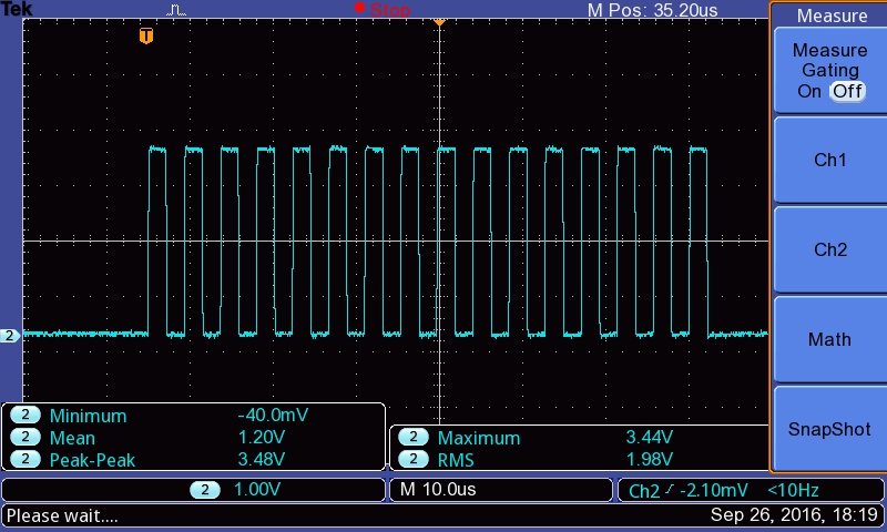
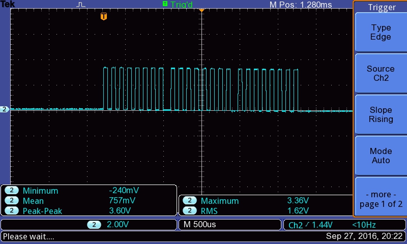
But the issue with this is,Clock signal is not generating on P1_5.

what can be the probable issue???

Regards

DC

  • Your code looks erratic. The following example defines MACRO to use SPI pins which define P1_5 as CLK, P1_6 as MOSI, P1_7 as MISO, and P1_3 as SS.

    /* ----------- XNV ---------- */
    #define XNV_SPI_BEGIN()             st(P1_3 = 0;)
    #define XNV_SPI_TX(x)               st(U1CSR &= ~0x02; U1DBUF = (x);)
    #define XNV_SPI_RX()                U1DBUF
    #define XNV_SPI_WAIT_RXRDY()        st(while (!(U1CSR & 0x02));)
    #define XNV_SPI_END()               st(P1_3 = 1;)

    // The TI reference design uses UART1 Alt. 2 in SPI mode.
    #define XNV_SPI_INIT() \
    st( \
      /* Mode select UART1 SPI Mode as master. */\
      U1CSR = 0; \
      \
      /* Setup for 115200 baud. */\
      U1GCR = 11; \
      U1BAUD = 216; \
      \
      /* Set bit order to MSB */\
      U1GCR |= BV(5); \
      \
      /* Set UART1 I/O to alternate 2 location on P1 pins. */\
      PERCFG |= 0x02;  /* U1CFG */\
      \
      /* Select peripheral function on I/O pins but SS is left as GPIO for separate control. */\
      P1SEL |= 0xE0;  /* SELP1_[7:4] */\
      /* P1.1,2,3: reset, LCD CS, XNV CS. */\
      P1SEL &= ~0x0E; \
      P1 |= 0x0E; \
      P1_1 = 0; \
      P1DIR |= 0x0E; \
      \
      /* Give UART1 priority over Timer3. */\
      P2SEL &= ~0x20;  /* PRI2P1 */\
      \
      /* When SPI config is complete, enable it. */\
      U1CSR |= 0x40; \
      /* Release XNV reset. */\
      P1_1 = 1; \
    )

  •  I have copied the code given above but still not getting clock on P_5.

    Regards

    DC

  • How do you use those MACRO?
  • /* ----------- XNV ---------- */
    #define XNV_SPI_BEGIN() st(P1_3 = 0;)
    #define XNV_SPI_TX(x) st(U1CSR &= ~0x02; U1DBUF = (x);)
    #define XNV_SPI_RX() U1DBUF
    #define XNV_SPI_WAIT_RXRDY() st(while (!(U1CSR & 0x02));)
    #define XNV_SPI_END() st(P1_3 = 1;)

    // The TI reference design uses UART1 Alt. 2 in SPI mode.
    #define XNV_SPI_INIT() \
    st( \
    /* Mode select UART1 SPI Mode as master. */\
    U1CSR = 0; \
    \
    /* Setup for 115200 baud. */\
    U1GCR = 11; \
    U1BAUD = 216; \
    \
    /* Set bit order to MSB */\
    U1GCR |= BV(5); \
    \
    /* Set UART1 I/O to alternate 2 location on P1 pins. */\
    PERCFG |= 0x02; /* U1CFG */\
    \
    /* Select peripheral function on I/O pins but SS is left as GPIO for separate control. */\
    P1SEL |= 0xE0; /* SELP1_[7:4] */\
    /* P1.1,2,3: reset, LCD CS, XNV CS. */\
    P1SEL &= ~0x0E; \
    P1 |= 0x0E; \
    P1_1 = 0; \
    P1DIR |= 0x0E; \
    \
    /* Give UART1 priority over Timer3. */\
    P2SEL &= ~0x20; /* PRI2P1 */\
    \
    /* When SPI config is complete, enable it. */\
    U1CSR |= 0x40; \
    /* Release XNV reset. */\
    P1_1 = 1; \
    )


    The above part i have defined globally.

    //To initialize SPI-

    void spicommunicationinit(void)
    {
    XNV_SPI_INIT();
    }

    // receive code

    uint16 spiRead(uint8 addr)
    {
    uint16 data;
    uint8 higherbyte;
    uint8 lowerbyte;

    printf("\n spi read");

    XNV_SPI_BEGIN(); // begin transmission

    XNV_SPI_TX(addr); // send addr

    XNV_SPI_WAIT_RXRDY(); //wait till received byte is ready

    higherbyte = XNV_SPI_RX(); // copy received byte

    XNV_SPI_WAIT_RXRDY(); //wait till received byte is ready

    lowerbyte = XNV_SPI_RX(); // copy received byte


    printf("\n higher byte=");
    printf("%x", higherbyte);

    printf("\n lower byte=");
    printf("%x", lowerbyte);

    return (data);
    }


    // Transmit code

    void spiWrite(uint8 addr,uint8 higherbyte, uint8 lowerbyte)
    {
    printf("\n \t spi write");

    XNV_SPI_BEGIN(); // begin transmission

    XNV_SPI_TX(addr); // send addr

    XNV_SPI_TX(higherbyte); //send higher byte

    XNV_SPI_TX(lowerbyte); //send lower byte

    XNV_SPI_END(); // End transmission
    }
  • Those MACRO are for SPI master which is sender of SPI. I suggest you to test your spiWrite to see if there is clock signal on P1.5 first.
  • yes I m getting clock now when "spiwrite" executes.

    but I m not getting correct data in "spiRead"
  • For running SPI slave on CC2530, you will need other driver. You can refer to Projects\zstack\ZNP\CC253x\Source\znp_spi.c
  • NO, Iwant to configure cc2530 as MASTER and write data into slave device(ATM90E26) and also want to read data from it
  • If so, you only use SPI master mode which you can do it based on XNV_SPI_XXX driver.
  • where is "XNV_SPI_XXX " driver is defined???
  • I mean to use the following MACROs

    XNV_SPI_BEGIN(); // begin transmission

    XNV_SPI_TX(addr); // send addr

    XNV_SPI_TX(higherbyte); //send higher byte

    XNV_SPI_TX(lowerbyte); //send lower byte

    XNV_SPI_END(); // End transmission
  • Hello,
    In SPI communication after initializing SPI PORT ,should I get clock signal on SCLK pin continuously or only when some data is transferred ???

    DC
  • You only get SCLK signal when you do SPI write or read.
  • Hello,
    while data transfer in SPI, i always get 16 cycles on SCLK pin but i should get 24 cycles on SCLK pin while data transfer.
    what modification should I do so that i can get 24 cycles on SCLK pin??

    Regards
    DC
  • Can you show me how you do to transfer 24 SPI bytes?
  • XNV_SPI_BEGIN(); // begin transmission

    XNV_SPI_TX(0x20); // send addr
    XNV_SPI_WAIT_TXRDY();

    XNV_SPI_TX(0x56); //send higher byte
    XNV_SPI_WAIT_TXRDY();

    XNV_SPI_TX(0x78); //send higher byte
    XNV_SPI_WAIT_TXRDY();

    XNV_SPI_END(); // End transmission
  • I only see you call XNV_SPI_TX(0x20), XNV_SPI_TX(0x56), and XNV_SPI_TX(0x78) which would only send 3 bytes, 0x20, 0x56, and 0x78 from SPI master.
  • for sending 3 bytes i should get 24 clock cycles on SCLK pin but I m getting only 16 clcock cycles on SCLK pin.
  • I suggest you to trace those SPI TX command line by line to see which one doesn't send SCLK.
  • one more thing i only get clock on SCLK PIN when i use debug mode,without debug mode i didn't get clock on SCLK pin.
  • Try to call XNV_SPI_INIT() right before you want to use SPI.
  • I have tried everything but I always get maximum 16 clock cycles on SCLK pin while SPI transfer.
    I should get 24 clock cycles as per my requirement.
    IS there any limitation in cc2530 SPI??
    if not then plz help me to resolve the issue.

    Regards
    DC
  • As I know, there is no limitation on SPI interface of CC2530. Have you debug step by step to know which SPI TX command doesn't send SCLK signal?

  • first two SPI TX command after SPI BEGIN always sends SCLK signal after two SPI TX command third SPI TX command does not send SCLK signal , i m getting why it is happening.
  • If you try the following code, do you see correct SCLK signal?

    XNV_SPI_INIT();
    XNV_SPI_BEGIN(); // begin transmission

    XNV_SPI_TX(0x20); // send addr
    XNV_SPI_WAIT_TXRDY();
    XNV_SPI_END(); // End transmission

    XNV_SPI_INIT();
    XNV_SPI_BEGIN(); // begin transmission
    XNV_SPI_TX(0x56); //send higher byte
    XNV_SPI_WAIT_TXRDY();
    XNV_SPI_END(); // End transmission

    XNV_SPI_INIT();
    XNV_SPI_BEGIN(); // begin transmission
    XNV_SPI_TX(0x78); //send higher byte
    XNV_SPI_WAIT_TXRDY();
    XNV_SPI_END(); // End transmission
  • let me test and will let you know.
  • I tried the code given.

    I am still getting 2 clock cycles only. Now what are my options.

  • If you use IAR to run step by step, which SCLK is missed, 0x20, 0x56, or 0x78?
  • When I write
    XNV_SPI_INIT();
    XNV_SPI_BEGIN();
    XNV_SPI_TX(0x20);
    XNV_SPI_TX(0x56);
    XNV_SPI_TX(0x78);
    XNV_SPI_END;

    I receive the following output at slave device
    20
    78
    20
    78
    20
    78
    20
    78
    3
    C1
    4
    4
    4
    F
    4
    F
    4
    F
    3
    C1
    3
    C1
    3
    3
    3
    3
    C1
    4
    F
    4
    F
    4
    F


    In Contrary if I write

    XNV_SPI_INIT();
    XNV_SPI_BEGIN();
    XNV_SPI_TX(0x20);
    XNV_SPI_WAIT_TXRDY();
    XNV_SPI_END();

    XNV_SPI_INIT();
    XNV_SPI_BEGIN();
    XNV_SPI_TX(0x56);
    XNV_SPI_WAIT_TXRDY();
    XNV_SPI_END();

    XNV_SPI_INIT();
    XNV_SPI_BEGIN();
    XNV_SPI_TX(0x78);
    XNV_SPI_WAIT_TXRDY();
    XNV_SPI_END();

    20
    78
    20
    78
    20
    78
    20
    78
    20
    78
    20
    78
    20
    78
    20
    78
    20
    78
    20
    78
    20
    78
    20
    78
    20
    78
    20
    78
    20
    78
    20
    78
    20
    78

    Please help why 0x56 is missing ?

    Also I did something like below

    spiWrite(20);

    spiWrite(30);

    spiWrite(40);

    spiWrite(50);

    spiWrite(60);

    spiWrite(byte b)

    {

    XNV_SPI_INIT();
    XNV_SPI_BEGIN();
    XNV_SPI_TX(0x20);
    XNV_SPI_WAIT_TXRDY();
    XNV_SPI_END();

    }

    I get output as follows


    20

    60

    20

    60

    20

    60

    20

    60

    20

    60

  • If you change 0x56 to other value like 0x54, does it work?
  • No it doesn't work. If I introduce MicroWait(t) even after calling, XNV_SPI_END() [ I tried from t = 4 to t = 100] data is mostly corrupted while receiving at Slave side (So I am unable to understand what is happening). I tried following code today with t = 1000.

    spiWrite(40);

    MicroWait(1000)

    spiWrite(50);

    MicroWait(1000)

    spiWrite(60);

    spiWrite(byte b)

    {

      XNV_SPI_INIT();

      XNV_SPI_BEGIN();

      XNV_SPI_TX(0x20);

      XNV_SPI_WAIT_TXRDY(); //Tried with and without this statement, didn't make any difference.

      XNV_SPI_END();

    }

    I received correct data for sometime at slave but it started showing wrong data after some time.

    When I observed the clock cycles, I got 24 cycles, but still there is issue of corrupted data.

    Hence I see there is some issue with SPI. In sample apps, while communicating with LCD, they used byte by byte data sending mechanism. I tried same above by introducing MicroWait(t) function. Kindly help.