This thread has been locked.

If you have a related question, please click the "Ask a related question" button in the top right corner. The newly created question will be automatically linked to this question.

CC2650 Bootloader Entry Problem

Other Parts Discussed in Thread: CC2650

I am utilizing the bootloader functionality where I'm turning on the back door entry, and using DIO3 set to active high for entry.  I have an external 10k resistor pulling this pin low to set the normal state.  What I’m seeing is that when the CC2650 first powers on or gets a reset, DIO3 glitches high, putting it into bootloader mode.  I changed the pull down to 7.5k, and it seems to work as expected (boots from flash).  I’m a bit skeptical of blindly accepting this change, because I’m not confident that it solves the problem in all scenarios since I don’t know what’s causing the glitch in the first place.  

The data sheet states that this pin is set to default input with no pull ups enabled.  So, what could be causing this?

Could anyone provide any insight into this?

  • DIO3 is UART_TX pin of backdoor boot loader and I don't see why it affect enable/disable boot from flash or serial boot loader. The pin to control this should be DIO11 so I suggest you to check DIO11.
  • I should have mentioned that I'm using the QFN32 5x5 package, where the default UART is on pins DIO0 and DIO1. My understanding is that the boot loader entry pin can be set to any of the IOs, in which I've set it to DIO3. I'm able to get the boot loader functionality to work in this configuration, but requires a strong pull down (<10k) on the boot loader entry pin (DIO3) to get the device to boot from flash. I need to settle on a value for this pull down that will work in all operational conditions and across all devices, and would like to understand why this is.
  • According to Table 13. Application Example IO Configuration in section 4.1.2 Bootloader Backdoor of swra466a CC2538/CC26xx Serial Bootloader Interface, the pin for backdoor boot loader is DIO9 not DIO3 when you use QFN32/5x5.

  • swra466a shows an example of the implementation of the boot loader based on the configuration set in its firmware, but this is not the only way. The technical reference manual, in section 8.1.2 (www.ti.com/.../swcu117) states that the back door entry pin is configurable in the CCFG. I'm able to get this part to work (mostly) using DIO3, but requires a strong pull down resistor to set the default state of the entry pin to low.
  • OK, I see. Since backdoor enable pin is responded to active low, why don't you just ground it when you want to enable backdoor? You can refer to LV_BTN_SELECT in Smart06EB schematics.

  • Actually, the boot loader entry is set to active high in my system.  This is why I have a pull down resistor to set the default state to low, so that the firmware runs from flash in normal operation.  I only want to access the boot loader for firmware upgrades.  I do this by plugging in an external interface that drives the DIO3 high, resets the MCU, and communicates over the UART.

    So, back to my original question.  Why doesn't a 10k pull down resistor set the state of this pin low on reset?  Something internal to the MCU is pulling this pin high on reset, putting the device into boot loader mode when nothing external is attached.  A 7.5K seems to do the job, but will this work over temperature, supply voltage range, lot to lot variation, etc.?

  • Can you provide schematics for this part?
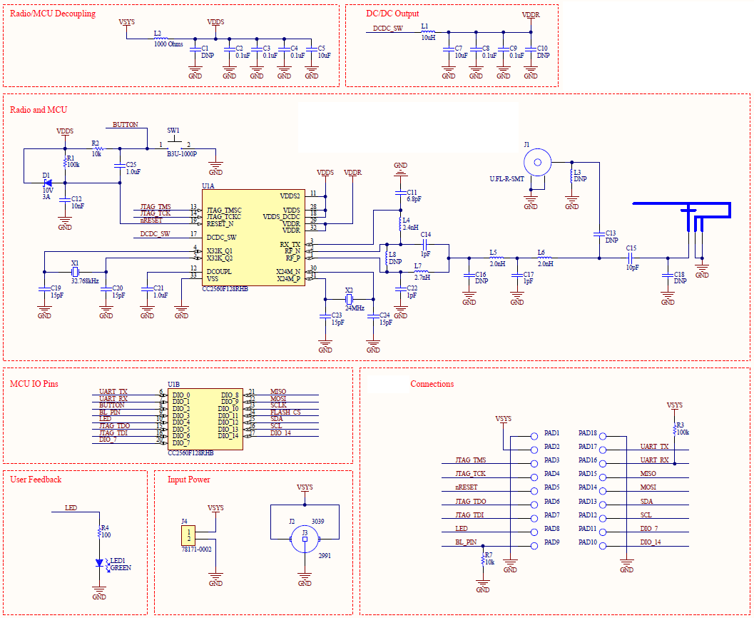
  • Here is the schematic of the relevant parts of my design.  It is essentially just a radio with connections to the outside world (PAD1 to PAD18).

  • Can you show what your BL_PIN connects to? If it is floating, I think 7.5K pull-down resistor should be fine.
  • This radio will be used in multiple products. Some that are a stand alone radio, where this nothing external is connected to PAD1-PAD18, hence the requirement for the pull down resistor R7 to set the state of the boot loader pin. What I'm really looking for is an explanation as to why the 10k pulldown doesn't work. Why do you say that the 7.5k pull down should be fine? Is there data to back this up?
  • Can someone from TI please help with this one?  The behavior of the MCU appears that directly out of reset the GPIOs are initialized with pull up resistors turned on for a few CPU cycles, which is contradictory to the reference manual.  I'd like to understand what the internal pull up resistor value range is so I can design my circuits adequately.  I can't seem to find this information in the data sheet.

  • It doesn't make sense that 7.5K pull-down resister works but 10K not. I suggest you to use multimeter to check your BL_PIN to see if there is any difference when you connect 7.5K and 10K pull-down resister.