This thread has been locked.

If you have a related question, please click the "Ask a related question" button in the top right corner. The newly created question will be automatically linked to this question.

CC2530 Flash Corruption

Other Parts Discussed in Thread: CC2530

Hello,

I'm facing a strange problem with CC2530.

Before I start, let me point some facts:
- I'm using a proprietary firmware with proprietary protocol (Not Z-STAK nor RF4CE)
- I'm using a proprietary bootloader with UART commands and WIRELESS commands.
- This product is on the market for a couple of years and this issue is happening sporadically.

Here  is whats is happening:

When we receive the product for technical assistance, the CC2530 is not working and we start an investigation process. The CC Debugger recognizes the chip and I can read the IEEE Address. So I know the CC2530 is working properly.
We try to connect with the bootloader Over the Air and Over Cable (USART). The bootaloader does not respond.
We procced with a "read flash into hex-file" and compare to a golden hex-file with the same bootloader version and application version.
If I rewrite the bootaloder using CC Debugger, the devices gets full operational again.

This issue happened other times but the investigation process was only made in the last two devices with this problem.

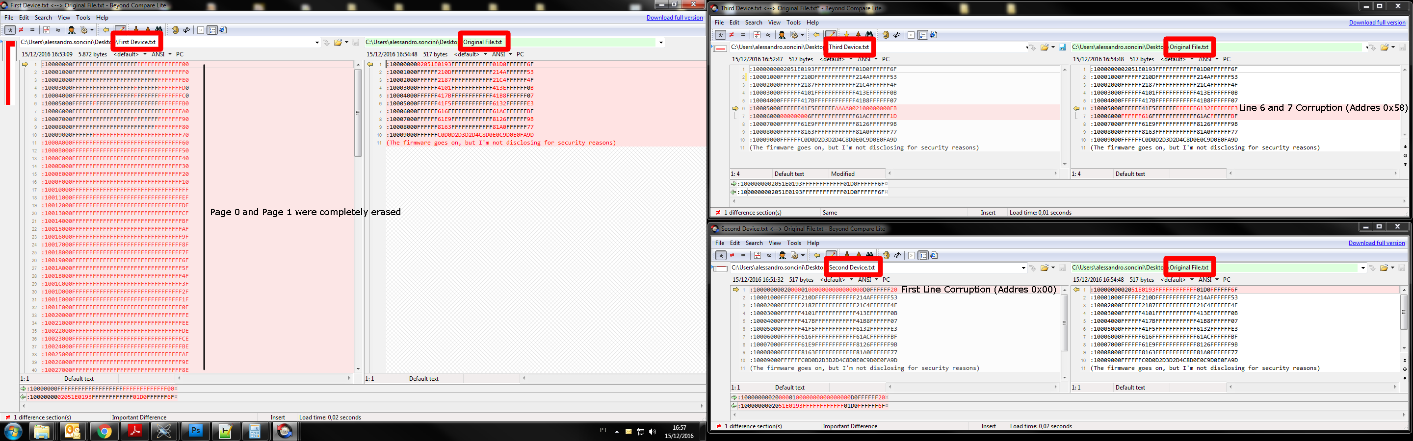
Problematic Device 01:
By analyzing the hex-file we could see that the first 2 pages were erased. The first 2048 bytes were displayed as 0xFF in the hex-file. So it will be 2048 NOPs until the first valid byte appears.
Here is the first line of the problematic hex-file:
:10000000 FFFFFFFFFFFFFFFFFFFFFFFFFFFFFFFF 00
And here is the first line of the golden hex-file:
:10000000 02051E0193FFFFFFFFFFFF01D0FFFFFF 6F

Problematic Device 02:
By analyzing the hex-file we could see that the 11 bytes of the 16bytes from the first line of the hex-file were different. Not just different, but the bytes were replaced by 0x00. So the first jump will point to address 0x0000.
Here is the first line of the problematic hex-file:
:10000000 020000010000000000000000D0FFFFFF 20
And here is again the first line of the golden hex-file
:10000000 02051E0193FFFFFFFFFFFF01D0FFFFFF 6F

Is it possible that a voltage spike, a brownout (not enough to reset de device) or a current surge could modify the values in the flash or change the values inside the RAM?

When the Problematic Device 01 appeared I thought that It could be an error in the bootloader firmware, but since Problematic Device 02 appeared I'm starting to think that this behavior is not a firmware problem but a CC2530 problem related to an abnormal condition.

Could someone please give me some detailed enlightenment about the behavior of the RAM and FLASH in abnormal condition like over voltage, under voltage, radiated EMI, ripple on the VCC line, etc.
Is there any condition that the problem described above could ever happen?

Thanks.

  • Alessandro Soncini,

    To me it sounds like an undervoltage issues. When the device is changing values in the flash it needs to startup a Flash voltage pump to generate the voltages needed to reflash itself. During the phase the device voltage must be above the stated minimums in that datasheet or you right flash corruption. The best way to to have the bootloader verify that the supply voltage is above a limit and add some margin (because the flash pump will draw more current). I see 2-300mV typically used as a required margin.

    Regards,
    /TA
  • Ta,

    Thanks for your answer, however, it doesn't make sense to me.

    The CC2530 User Manual, on topic 5.1 says:
    The BOD protects the memory contents during supply voltage variations which cause the regulated 1.8-V power to drop below the minimum level required by digital logic, flash memory, and SRAM.

    If an undervoltage event happens, the system will reset.
    I'm aware that BOD could happen during the flash write or erase, but it will not write some random bytes. It will write the correct bytes until a BOD occur. As the flash writes 4bytes at once, I understand that a BOD event during a flash write would corrupt only the 4 bytes been written.

    Are you assuming that CC2530 has a BOD issue? Or the BOD threshold is lower than the voltage needed to operate the flash correctly?

    Thanks.
  • Just now another product came up with the same problem.

    I really need some help here and I'm willing to disclose a lot of information and effort to investigate and eliminate this problem.

    I'll not stop posting here until I can solve this problem.

    So now I have 3 products that show the same problem.

    -The first one came up with page 0 and page 1 erased.

    -The second came up with 10 bytes corrupted in the first 16 address. The corruption is not sequencial. The first byte was ok, the second and third were corrupted (0x00) the fourth was ok.

    -The third came up with 12 bytes corrupted starting at address 0x58, this time, all sequential.

    I read the flash of each device using SmartRF Flash Programmer (Read flash into hex-file)
    I compared each corrupted Hex-file against the original Hex-file.

    The result is attached to this post and also available at the link below:
    i.imgsafe.org/2ea4140581.png

    Here are some notes about my application.
    -I'm using IAR Workbench.
    -Our bootloader uses the RF, RF_ERROR, TIMER4, USART0_RX, USART1_RX interrupts. All other unused interrupts are mapped in a .c file like this:

    __interrupt void isr_TMR1_VECTOR(void) 
    {
        return;
    }

    -Our application uses an offset of 0x5000 so the application interrupts are mapped from 0x5000. When an interrupt occurs, the booatloader checks whether the stack pointer was above 0x5000 and redirect the interruption call.
    -I have a function named "flash_page_erase(uint8 page)" but I can guarantee that the variable "page" is never ZERO. Inside this function, I'm checking if the page variable is higher than than the last page reserved for the bootloader. Below follow the snippet:

    uint8 flash_page_erase(uint8 page)
    {
        uint8 flag_timeout_dma=0;
    
        if(page < 0x0A) //Do not allow an erase action on the pages where the bootloader is stored. 
            return(0xE1);
    ...(The function goes on) }


    -The application does not use the flash. It doesn't have the libraries and routines to read/write/erase the flash.
    -Inside the function "void flash_write(uint32 addr, uint8 *ptr_data, uint16 size)" I'm checking whether the variable "addr" is within the bootaloder code area.

    if( (addr < BOOT_CODE_SIZE) || (addr > FLASH_SIZE) ) //Atempt to write within bootloader code area or to an address bigger than the flash size
    {
        return(1); //Error, address not allowed.
    }


    -The only way the bootloader could ever write his own flash space would be by RAM corruption when setting the DMA address.

    What i think it's really weird is the fact that the flash write command only writes in blocks of 4 bytes and I'm getting sometimes 2 bytes corrupted and 2 bytes intact. As below:
    Original: 02 05 1E 01
    Corrupted: 02 00 00 01 (The value 0x02 is at the address 0x00 of the flash)


    TEXAS, I really need your help here. The explanation TA12012 gave me doesn't make sense since the chip has a brown-out detector and would reset before any flash issue.
    Since the bootloader jumps to the application area, the only flash_write event that could occur would be a command to send a new firmware, and that is not the case. The bootloeader by itself just execute flash read commands.
    To execute a flash write, an externar event, like a USART command with the right CRC or a RF packet also with a valid CRC.

    I really need some help here.

  • Someone? Texas? I could use some support here.
  • Hello Alessandro,

    I have observed the same problem and my code does not even have any capability to alter

    the flash memory. The memory is just erased apparently out of nowhere.

    Have you solved your problem  already? If so, how? If not, we really need some

    help from TI staff!

    Regards,

    Aldo.

  • Hello Aldo,

    Unfortunately I didn't solve my problem yet.

    As you can be imagining, this is probably an IC issue and will probably generate an errata.

    I can't stress  enough how disappointed I'm with the way Texas service us with technical support.

    Besides this thread, I've emailed Texas and I was able to get a Ticket support number, but I can't check the status, it's just a number for me since I can't do anything with it.

    I'm waiting for a reply since 8 Dec. and I've been emailing Texas about this problem every week now. I was speaking to Naser Salameh who gave this Service Request number #1-2546430600.

    The last reply I got was on Jan, 18. Since then, I'm being ignored.

    It's hard to develop using Texas' products because whenever you need their help, good luck, you need to solve it by yourself.

    This is not the first time I reach Texas support for help and end up being ignored. 

    Being ignored is Texas Instrument's standard procedure.

    I have provided a lot of information and spent a lot of time investigating and gattering information to opening this thread, but it's useless.

    TEXAS SIMPLY DOESN'T HELP.

    I'm trying to run away from texas' products as much as I can, but some of our products has a legacy and I can't replace the ICs yet. But someday I will.

    @TEXAS_INSTRUMENTS

    How can I get some minimal support over here. Now it's not just me complaining about this problem, and I have seen some other threads with the same issue.
    You need to give your clients some feedback! URGENTLY.
    It has been almost 3 month. 3 MONTHS.

  • Do you see this issue when CC2530 is powered by battery or by DC power supply? If it is powered by battery, it might be undervoltage issues as TA said. If it is D.C. Power, it shouldn't be undervoltage issues and there might be other reason causes this.
  • Alessandro,

    I did not want to mention it before, but I am quite confident that it is an IC problem, as you
    pointed out. I cannot see other possible cause at the moment. I have been working with this
    chip since 2012, and have installed an electrical energy metering network, composed
    of roughly 100 nodes. They have been operating out on the field since 2014, and so far
    I have seen two or three device failures of the type we are discussing here, about 2% to 3%
    failure rate. This failure rate could be associated to low quality manufacturing processes,
    but let us the TI guys explain to us what is going on. But suppose there is a problem
    with my code or the power source or any other problem that you can imagine, then
    why only 3 nodes out of 100 have failed after 2 years of continuous operation?
    (They have all being programmed in the same way and are subjected to identical
    conditions) Applying plain logic the conclusion seems to be that those 3 IC's have to be
    faulty. The question then is, can we do something to avoid the flash corruption problem?
    Perhaps using the flash locking bits?

    I did not complain before because our current network serves my institution only and
    I could easily collect the faulty nodes and reprogram them, then sent them back to the
    field. But now, a company has paid for our consulting services and they do not want this
    kind of errors. So I need to have a definite answer quickly.

    YK Chen,

    I have used both batteries and dc power supplies, and the fault has ocurred with dc
    power supplies. But I think that it is not an issue of the power supply.
  • If this issue happens on DC powered devices, I would say this shouldn't be undervoltage issues. Hope someone from TI can help you out.
  •  

    Are you and TA saying that the Brown-out detection has a threshold that could corrupt the flash data before taking action? Or the Brown-out can only protect the processor and leave the peripherals unprotected?

    Lets assume for a moment that the problem is the undervoltage. If I'm not writing or reading anything to/from the flash, this undervoltage situation could corrupt the data?


    I'm going to use the Lock Bits from now on, but it will be very difficult to measure its efficiency. If the problem occurs, I will not be able to read the flash to be sure if it's the same problem or a new one. But we need to try something right?

  • If you are not writing (reading doesn't corrupt Flash) anything to the flash, this undervoltage situation couldn't corrupt the data.
  • Hi Again,

    Two more devices have gone down now. This is a really annoying problem!!!

    I reflashed them and became operational again. But it seems that the percentage

    of faults is raising!!!


  • Aldo,

    I've noticed that all my defective devices were PCB assembled starting on 15 Oct, however, I don't know if my Contract Electronics Manufacturing bought new ones or used old ones from their remaining stock.

    I will try to track the IEEE Address from my chips in order to check if there is a pattern or a chronological linearity.

    And since no one from Texas shows up, I will try to summon:

    Could you all be so kind and read the whole thread? As you all can see, we are not getting any help in this issue.

    TA12012 (556214)


  • hi Aldo,

    I'm not the maximum expert of CC2530, but from your description I read so far, the root cause doesn't look to be related to the part itself, but mainly by (typical cause of flash corruption in general) an undervoltage or spike (like an ESD event or a supplier that doesn't blocks the HF contents of the switching) that hit the part...

    the root could then be found in:

    a) a marginal design (protection missing, bad layout, marginal power supply design...)

    b) a quality problem, that articulates in:

    - bad handling of the part

    - changes in the manufacturing/assembly process

    - actual bad parts shipped (not screened out at the testing)

    Now for the info you provided and what is my experience in these kind of failure, I can tell you that the last one is the least possible one (you can raise a sample verification to be sure the parts are ok, but this won't help you much...

    I would rather (since the defective parts are dated > Oct.-15) check if the ICs have the same datecode (i.e. comes from the same production batch/line):

    a) if yes then we can assume it is a quality problem, but all the 3 sub-cases are still possible

    b) if not, then the root cause is most likelt in the handling/manufacturing/assembly process

    I could also double check your system (the power and potential weakness, in case), just let me know.

    KR

    Vincenzo

  • Hello Vincenzo,

    Thank you for your answer.

    I have a few more doubts and I hope you can answer them.

    1- CC2530 has a Brown-Out Detector.
    From the datasheet we have:
    "The BOD protects the memory contents during supply voltage variations which cause the regulated 1.8-V power to drop below the minimum level required by digital logic, flash memory, and SRAM."
    From my undestanding, the BOD will protect the flash against undervoltage, but you all are saying that an undervoltage could corrupt the flash.
    Does CC2530 BOD protects the flash?

    2- These flash corruptions caused by ESD, undervoltage or any other unknown event could corrupt the flash even if there is no activity(read/write)?

    3- The flash lockbits will prevent this corruption events from happening?


  • Hello Vincenzo,

    Thank you very much for your response,

    I will be carrying out some tests on the radios during the weekend and will come back with

    the results next monday. Your answer appears sound to me, and yes, anyone of the three possibilities

    that you describe could be the root cause. So let us proceed step by step.

    I have two different assembly batches, and will compare 5 radios form the first assembly

    against 5 radios of the second assembly (the one that has caused us more problems).

    I will focus on the power supply and will verify the stability of clocks (we have the clock loss detector enabled)

    to see if there is any correlation with the flash issue (perhaps the supply is badly regulated and this affects the stability

    of the clocks, and as you have written it could also corrupt the flash). Both assemblies have the same layout

    but were assembled at different times. If during the test the batches perform similarly then

    we could assume that it is probably a layout problem. Otherwise it could be an assembly problem

    that has affected the second batch.

    In the meantime, it would be very nice if you could answer Alessandro's questions:

    >1- CC2530 has a Brown-Out Detector.
    >From the datasheet we have:
    >"The BOD protects the memory contents during supply voltage variations which cause the regulated 1.8-V power to drop below the minimum level required by digital logic, flash memory, and SRAM."
    >From my undestanding, the BOD will protect the flash against undervoltage, but you all are saying that an undervoltage could corrupt the flash.
    >Does CC2530 BOD protects the flash?

    >2- These flash corruptions caused by ESD, undervoltage or any other unknown event could corrupt the flash even if there is no activity(read/write)?

    >3- The flash lockbits will prevent this corruption events from happening?

    Best Wishes,

    Aldo.

  • hi Aldo,

    with reference to your question I would say:

    1) the brown out protection is to prevent flash corruption that are very likely to happen when the supply rises slowly, so it is mainly at the start-up and/or for slow events
    2) potentially yes
    3) this honestly, I don't know

    have also a look at e2e.ti.com/.../92849 that discuss the same topic for another part

    hope this helped a bit
    KR
    Vincenzo
  • Hi Vincenzo,

    Thank you very much for spending some time to replying to this thread, it was very helpful.

    Thanks again.

    Alessandro Soncini.