This thread has been locked.

If you have a related question, please click the "Ask a related question" button in the top right corner. The newly created question will be automatically linked to this question.

CC2530ZDK-ZLL: Source Code for Light Link Development Kit

Part Number: CC2530ZDK-ZLL
Other Parts Discussed in Thread: Z-STACK, CC2531, CC2530

Hello,

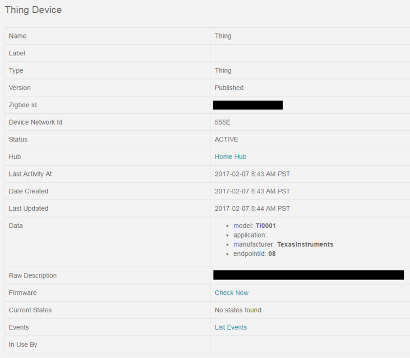
I just received the light link development kit and my main goal is to try to get the device to pair with a Samsung SmartThings hub.  I realize I'm probably several steps away but I'm trying to find the best path to fill in the knowledge gap between where I am and where I need to be.  

Right now, i can run the demo and see what's being sent in the packet sniffer but, unfortunately, it doesn't yet mean much to me.  I think a good first step would be to be able to see the code that is currently being run and try and figure out how it's creating the messages, their purpose, etc, and then try and correlate it to zigbee standards documents so I can understand which parts of the code are doing what, how the zigbee stack operates, etc.  Unfortunately, I'm still at the stage where I don't really know what I don't know.  I definitely don't mind doing the research but a little guidance will likely go a long way!

Is the source code for both the zlight2 RGB lights as well as the remote (ZLLRC) available?  

Also, if you can recommend a learning path/documents to read up on to help me accomplish my goal, it would be greatly appreciated!  Thanks for all your help!

  • SmartThings hub runs Zigbee HA profile. There's a SampleLight example (Zllight router configuration) in Z-Stack Home 1.2.2a and you can build and download it to your zlight2 to join SmartThings hub. There are development user guide in Z-STack Home document folder and you can study it first.
  • YiKai, thanks for pointing me in the right direction!  I have the hex code all burned to the Zlight board but the SmartThings hub doesn't appear to be seeing it.  Is there something that needs to be done on the zlight board to put it into discovery mode?  I know with the Sylvania bulb, I had to reset it 5 times or something to that effect.  I tried doing that with this board (using the reset button) but it's still not quite detecting it.  

    I did select the RouterZlight configuration in the workspace using Zstack Home 1.2.2 but I'm not sure if there's another step (I know the root file was for the CC2530DB but I assume that this particular project was specifically for the Zlight, based on the name).  Is there a configuration setting I need to change or some procedure I'm missing?  

    As far as the documentation, it looks like it's pretty well organized so I'm definitely looking forward to filling in some of these knowledge gaps once I have a code that's proven to be working (I'm assuming this one does as well, I'm just missing an important step somewhere).  

    Any help you can give me would be appreciated.  Thanks!

  • Try to remove HOLD_AUTO_START from compile options when you build SampleLight example for Zllight2 to test again.
  • Yikai,

    I removed HOLD_AUTO_START from Options->C/C++ Compiler/Defined Symbols and rebuilt it but haven't had any luck, unfortunately. Is this the location you were referring to or is there another place I should be removing this as well?

    Unfortunately, it still doesn't seem to detect it. Even tried pressing the reset button, holding it for a few seconds, then releasing it about 5 times but no luck there.
  • Try to change "-DDEFAULT_CHANLIST=0x00000800" in f8wconfig.cfg to "-DDEFAULT_CHANLIST=0x07FFF800" and rebuild it to test again.
  • Well, it looks like that worked!  It's showing up as "thing" right now and doesn't yet have any functionality.  I had a few questions though:

    1)  What did the HOLD_AUTO_START function do and should I add it back in?  I've tested it with it in and out and it detects it either way after the default frequency is changed

    2)  Why did changing the default frequency work with this configuration?  I noticed my router is setup as channel 20, so I updated the line in the code to be "-DDEFAULT_CHANLIST=0x00100000  // 20 - 0x14" and that seems to work.  Should I leave it at the frequency you suggested or set it to the correct band?  

    3)  One of the compilation options is WHITE_LED_ONLY.  Does this mean this device is setup as a white LED and not an RGB led?  And if so, is it possible to change the configuration to support RGB?

    3)  How did you guys test the functionality of the router configuration?  Do you have a SmartThings app that was created to test it or was it just tested to see if it could be picked up by SmartThings?  And if there is an app, do you have the sample code so I can import it into SmartThings and verify functionality?

    Thanks for all your help!  It looks like I'm almost there!  

    Edit:  Changed question #2 from "Why did changing the default frequency work?  Is this the default frequency of SmartThings or is the lower frequency likely not working for another reason (noise, interference, etc)" once I saw my router was setup as channel 20

  • I uploaded some pictures of a working device and TI's device and there are definitely some things missing, one of the big ones that stands out is the application (not sure if that's how it tells what kind of device it is). I tried looking through the files to find where some of this is defined but there's no "search project" or something like that and there are way too many *.c and *.h files in this project to open every one . . . Below are pictures of a working Lightify device and the profile of this TI device:

    TI's profile:
    i9.photobucket.com/.../TI-Zigbee 02-07-17_1.png

    Lightify's profile:
    i9.photobucket.com/.../Lightify-Zigbee 02-07-17_1.png

    Thanks!
  • 1. HOLD_AUTO_START enable would make device keep on HOLD state after power on. It mean device would do nothing and wait user to press a button to start everything.
    2. There are 16 channels that can be used by coordinator to form Zigbee network and I don't know which channel your SmartThings hub uses. So, I let you to enable your device to scan all of 16 channels when it starts and tries to join Zigbee network.
    3. If you define WHITE_LED_ONLY, it means this device is only setup as a white LED. If you don't define it, it would support RGB led.
    4. I would add some Zigbee routers and end device into a Zigbee network and use Ubiqua Packet Analyzer to check routing messages.
  • Yikai,

    Thanks for the response to each of those bullet points!  It sounds like based on what you said, I will definitely want to remove the WHITE_LED_ONLY and HOLD_AUTO_START from the compile options.  The fourth point left me a little but confused as to what the purpose of this project is.  

    Based on the above, is this project only meant to be detected by SmartThings (or any hub) or does it have any additional functionality?  My understanding is this was code designed for ZLight that would create a detectable RGB bulb but it now sounds like it's not actually setup for that (unless I'm misunderstanding something).  If that's the case, what is it that this code does and is it possible to set it up in a way that does work like an RGB bulb?  I guess I kind of expected the project to use the same functionality provided by the remote control (changing colors, setting up groups, etc).  

    Is there an example project available that does make use of this functionality (changing LED colors via hub, assigning to groups, etc)?  

  • Actually, if the implementation follows Zigbee HA profile, it should work with SmartThings or others' Zigbee HA compliance hub. For SmartThings hub, I know they might block some functionality according to manufacture name or ID in Zigbee basic cluster so SampleLight with LED colors might not work with it. Anyway, you can try it to know if color LEDs work with SmartThings hub.

  • Yikai,

    I think it might not have the functionality because the application portion is not actually described and, if this is the section that describes what the device does, it makes sense that it might not fully recognize it by what kind of device it is. If you look at my screenshots at the links I posted a few posts back, it shows the model, manufacturer, and endpointId, but it's missing the application description. I tried to locate where these were located in the code but couldn't find them (probably looking right past them).

    Do you know where these portions are described in the code? I think if I can locate this, I should be able to specify the application to be "01", which is what is used with Osram's lightify bulb and see if that helps.

    Also, do you know what this code was originally designed for and where it was used? I assume it was made specifically for the Zlight for a specific application and tested with some sort of hub (even if it's not the SmartThings one). I was just hoping to get more information about what should be working with this code and what it was designed to do (it appears it was configured as a white led bulb only, based on the configuration). Just trying to get a bit more information about what to expect or what I can test it against before moving it to the SmartThings hub. If it is an issue that is SmartTHings specific, I'd like to find out something else I can test it against before moving it to SmartThings.

    Thanks!
  • Zlight2 RGB lights and ZLLRC are designed for ZLL profile in the beginning so I suggest you can download and study Z-STACK-LIGHTING:1.0.2 to know better about its capability.

  • Yikai,

    I'm a bit confused. You say this board was designed for the ZLL, and I understand that, but the board itself has the capability to be controlled for different colors and to join different groups because that functionality was demonstrated with the remote. I checked out that link you sent and it had a Z Stack Lighting section but it also has a Z Stack Home section as well. Based on this, I believe you're saying one of three things:

    1) The chip can't run the home automation profile (which means I can't use this chip on future projects)
    2) The home automation stack software doesn't work in HA mode (which means I can't use this chip on future projects)
    3) The reference project itself doesn't work correctly (which means it needs someone to take a look at it to debug it so that it does or I can't use this chip on future projects)

    If it's either 1 or 2, it means this chip is non usable for me and I guess I need to look elsewhere. If it's 3, it means I need more support on this. Is it possible to contact the engineer that put this project together? Or is it possible the HA stack/example project was never fully tested?

    Please let me know when you get the chance because if I can't go any further, I need to find an alternative and look into returning this development kit. Thanks!
  • Your understanding is incorrect. CC2530/CC2531 supports both Zigbee HA and ZLL profile. In ZLL example, you can use RC to control RGB leds. In HA e ample, there is no host or GW reference design to show you how to control RGB leds. You have read Zigbee spec to do it by yourself.
  • Yikai,

    Perfect, this is more the kind of information I wanted to know!

    I don't have a problem doing some of this myself but what I still can't understand is what this project DOES do. I understand now that it doesn't control RGB leds, as you mentioned earlier and I know know that the ZLL example DOES control the RGB leds so I should be able to update this example so that it does this as well (even if it does make me wonder why this functionality wasn't added to this code if it's already been completed under another example).

    So if I'm to update this code, I need to understand what it DOES do and what else I need to do in this code vs the light link example. Can you at least tell me what it is the light link code does that this one doesn't (maybe that's not an easy question to answer and, if that's the case, i understand) and can you tell me what this code is setup to do so I know where to go next? Once again, I don't know what I don't know yet and that's what I hope to use the reference design for. If I don't know what the reference design does, I certainly don't know what I'm building from.

    I apologize if I sound frustrated, I'm just having trouble figuring out the reference design itself, I haven't even been able to dive into the code. If it was a straight forward analog (or even digital) chip, I could take a look at the voltages, the waveforms, and troubleshoot the signal. With it being a wireless unit, it's a bit more complicated to debug (at least to me) and using a software stack I'm not familiar with on a communication protocol I've never used before, filling in the knowledge gaps is difficult.

    Anyway, thanks for the help!
  • I agree it's frustrating and there is knowledge gaps you need to fill. My suggestion is to read Zigbee HA, ZLL, and ZCL spec first to understand better on how Zigbee profile and cluster works. Once you have better domain knowledge, you can start to map Z-Stack example into descriptions in spec.
  • Hi Jeremy,

    The Zigbee Light Link development kit was intended to be used with the ZigBee Lighting stack to achieve its full functionality. The "Z-Stack Lighting Sample Application Users Guide" provided with the ZigBee Lighting stack goes into more details about what functionality is available. The ZigBee Lighting stack uses the ZLL profile, which means when using this stack these devices (light, remote) are only compatible with other devices that use the ZLL profile.

    As you have seen, Z-Stack Home Automation 1.2.2a also has a project (SampleLight) that supports the ZLight2 board configuration. In this stack, the SampleLight project is only intended to show a very basic usage of the On/Off cluster, i.e. toggling an LED. You can read more about what functionality is available in the home automation sample apps by reading "Z-Stack Home Sample Application User's Guide".

    In short, if you intend to use the ZLight2 board with a HA Coordinator (SmartThings hub), you will need to use a HA stack, i.e. Z-Stack Home Automation 1.2.2a, and this stack only provides options for making bindings for basic On/Off functionality for this target device out-of-the-box.

    A good starting point to see the differences between the two projects would be to look at the clusters/attributes supported for each one, take a look at zcl_samplelight_data.c in SampleLight from Z-Stack Home and zll_samplelight_data.c in SampleApp from Z-Stack Lighting.
  • Hi Jeremy,

    This is a follow up to my original post. Turns out I was mistaken, the ZLL profile does support a "classical" commissioning mode apparently. Using Z-Stack Lighting 1.0.2 and the SampleLight - ZLight - Router configuration of the SampleApp project, you can read about how to put this device in Classical Commissioning mode in Section 4 of the "Z-Stack Lighting Sample Application User's Guide", which comes with the stack.

    Please read this section and try out this commissioning mode with your SmartThings hub and let me know how it goes.