This thread has been locked.

If you have a related question, please click the "Ask a related question" button in the top right corner. The newly created question will be automatically linked to this question.

CC2538DK: I2C communication with CC2538 on SmartRF06 Evaluation Board

Part Number: CC2538DK

Hi,
I am using CC2538 Dev Kit to develop my Zigbee smart home app for CC2538 using Z-Stack 3.0.
I searched in SmartRF06 Evaluation Board design it's looks like CC2538 I2c Lane is no where available to access.
How can I communicate with CC2538 I2c from external sensor via SmartRF06?
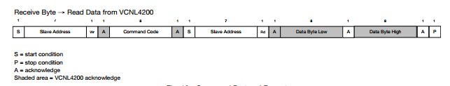
I mean, I have CC2538 Evalution module connected on SmartRF06, I have one more third party I2C sensor VCNL4200 (Light and proximity). VCNl 4200 is ready to talk with my master i2c with SCL and SDA. How can I connect my CC2538 I2C with this on SmartRF06 Evalution Board.

  • There's I2C example in cc2538 foundation firmware which you can download from www.ti.com/.../cc2538-sw
  • Hi,
    Thanks for the info, I2c talk is now happening between Master and Slave.
    How can I make my device VCNL4200 has slave now, please suggest any ways.
  • There's no I2C example dedicated for VCNL4200. You have to read VCNL4200 data sheet and do it by yourself.
  • Hi,
    How can I enable the SmartRF06 pins to I2C.
    I mean in this example it seems I2C is Assigned to GPIO pins, Like that I want to enable a pins which should direct me access from SmartRF06 it has many RF pins and other.
    My main intention is I want 2 pins SDA and SCL of I2C can access from SmartRF06 board.
  • You can refer to schematic in www.ti.com/.../swru321b.pdf
  • Hi Chen,
    How to enable I2C interrupt and configuring pin to I2c interrupt
  • I2C interrupt? I never heard of that.
  • Sorry, it was interrupt to I2c and may received by SDA only I think.
  • I2C doesn't work in this way. We usually do I2C write or read when I2C master wants to do it.
  • Hi chen,
    The example demonstrates only for Single send and Receive.
    How to send and receive the Burst Data.
  • It's working I got it. Thank you .
  • Hi Chen,

    I am trying to read data from my VCNL 4200, the read format is like

    So, I have to send the command: "0x08H_L", how to send commands in I2C.

    Please review my code too, I am using VCNL4200 demo board it has configure Pullup in board.

    #define EXAMPLE_PIN_I2C_SCL             GPIO_PIN_2
    
    #define EXAMPLE_PIN_I2C_SDA             GPIO_PIN_3
    
    #define EXAMPLE_GPIO_I2C_BASE           GPIO_B_BASE      
    
    #define SLAVE_ADDRESS 0x51      //Slave addr of VCNL4200
    
    int main(void)
    
    {
    
         uint32_t pui32DataRx;
    
         uint32_t i,x;
    
         char output[8];
    
       SysCtrlClockSet(false, false, SYS_CTRL_SYSDIV_16MHZ);
    
       //  The I2C peripheral must be enabled before use.
    
       SysCtrlPeripheralEnable(SYS_CTRL_PERIPH_I2C);
    
       // Do reset of I2C module
    
       SysCtrlPeripheralReset(SYS_CTRL_PERIPH_I2C);
    
       // Configure I2C pins
    
       GPIOPinTypeI2C(EXAMPLE_GPIO_I2C_BASE, EXAMPLE_PIN_I2C_SCL);
    
       GPIOPinTypeI2C(EXAMPLE_GPIO_I2C_BASE, EXAMPLE_PIN_I2C_SDA);
    
       // Configure pins as peripheral input and output
    
       IOCPinConfigPeriphInput(EXAMPLE_GPIO_I2C_BASE, EXAMPLE_PIN_I2C_SCL,
    
                               IOC_I2CMSSCL);
    
       IOCPinConfigPeriphInput(EXAMPLE_GPIO_I2C_BASE, EXAMPLE_PIN_I2C_SDA,
    
                               IOC_I2CMSSDA);    
    
       IOCPinConfigPeriphOutput(EXAMPLE_GPIO_I2C_BASE, EXAMPLE_PIN_I2C_SCL,
    
                                IOC_MUX_OUT_SEL_I2C_CMSSCL);
    
       IOCPinConfigPeriphOutput(EXAMPLE_GPIO_I2C_BASE, EXAMPLE_PIN_I2C_SDA,
    
                                IOC_MUX_OUT_SEL_I2C_CMSSDA);  
    
       HWREG(I2CM_CR) |= I2CM_CR_LPBK;
    
       I2CMasterInitExpClk(SysCtrlClockGet(), false);
    
       I2CSlaveEnable(); // TBD is this needed or done by I2CSlaveInit???
    
       I2CSlaveInit(SLAVE_ADDRESS);
    
       uint8_t masterSend = 0x08H_L; // error here, type not matching
    
       while(1){
    
       I2CMasterSlaveAddrSet(SLAVE_ADDRESS, false);
    
       I2CMasterDataPut(masterSend);
    
       I2CMasterControl(I2C_MASTER_CMD_BURST_SEND_START);
    
           I2CMasterIntClear();
    
           while(!(I2CSlaveStatus() & I2C_SLAVE_ACT_RREQ))
    
           {
    
           }
    
       I2CMasterSlaveAddrSet(SLAVE_ADDRESS, true);
    
       I2CMasterControl(I2C_MASTER_CMD_BURST_RECEIVE_START);
    
       printf("read start\n");
    
       while(!(I2CSlaveIntStatus(false)))
    
       {
    
         ;
    
       }
    
       I2CSlaveIntClear();
    
       while(!(I2CSlaveStatus() & I2C_SLAVE_ACT_TREQ))
    
       {
    
         ;
    
       }
    
           pui32DataRx = I2CMasterDataGet();
    
           sprintf(output, "%.1f", pui32DataRx);
    
           printf("rec = ");
    
           for(i=0; i<=sizeof(output); i++){
    
             printf("%c", output[i]);
    
           }
    
           printf("\n");
    
       }
    
    }

  • Sorry for disturb, To read I has to send " PS_Data"
    08H_L PS_Data_L
    08H_H PS_Data_H

    So, I think it's need to send 08H_L to read lower byte of sensor data and 08H_H for higher byte of sensor data, finally it's a 16 bit data. And it may be 0x08 and 0x08 has to send. is my understand is write.
  • According to my understanding to the datasheet, it should be send command 0x08 and you can read two continuous bytes which is PSPDATA_L and PS_DATA_H. 

  • #define EXAMPLE_PIN_I2C_SCL             GPIO_PIN_2
    #define EXAMPLE_PIN_I2C_SDA             GPIO_PIN_3
    #define EXAMPLE_GPIO_I2C_BASE           GPIO_B_BASE      
    
    //*****************************************************************************
    //
    // Number of I2C data packets to send.
    //
    //*****************************************************************************
    //#define NUM_I2C_DATA 3
    
    //*****************************************************************************
    //
    // Set the address for slave module. This is a 7-bit address sent in the
    // following format:
    //                      [A6:A5:A4:A3:A2:A1:A0:RS]
    //
    // A zero in the "RS" position of the first byte means that the master
    // transmits (sends) data to the selected slave, and a one in this position
    // means that the master receives data from the slave.
    //
    //*****************************************************************************
    #define SLAVE_ADDRESS 0x51      //Slave addr of VCNL4200
    
    
    //*****************************************************************************
    //
    // Configure the I2C0 master and slave and connect them using loopback mode.
    //
    //*****************************************************************************
    int
    main(void)
    {
          uint32_t pui32DataRx = 1;
          uint32_t i,x;
          char output[8];
          uint8_t masterSend;
    
        //
        // Set the clocking to run directly from the external crystal/oscillator.
        // (no ext 32k osc, no internal osc)
        //
        SysCtrlClockSet(false, false, SYS_CTRL_SYSDIV_16MHZ);
    
        //
        //  The I2C peripheral must be enabled before use.
        //
        SysCtrlPeripheralEnable(SYS_CTRL_PERIPH_I2C);
        
        //
        // Do reset of I2C module
        //
        SysCtrlPeripheralReset(SYS_CTRL_PERIPH_I2C);
    
        //
        // Configure I2C pins
        //
        GPIOPinTypeI2C(EXAMPLE_GPIO_I2C_BASE, EXAMPLE_PIN_I2C_SCL);
        GPIOPinTypeI2C(EXAMPLE_GPIO_I2C_BASE, EXAMPLE_PIN_I2C_SDA);
    
        //
        // Configure pins as peripheral input and output
        //
        IOCPinConfigPeriphInput(EXAMPLE_GPIO_I2C_BASE, EXAMPLE_PIN_I2C_SCL, 
                                IOC_I2CMSSCL);
        IOCPinConfigPeriphInput(EXAMPLE_GPIO_I2C_BASE, EXAMPLE_PIN_I2C_SDA,
                                IOC_I2CMSSDA);    
        IOCPinConfigPeriphOutput(EXAMPLE_GPIO_I2C_BASE, EXAMPLE_PIN_I2C_SCL,
                                 IOC_MUX_OUT_SEL_I2C_CMSSCL);
        IOCPinConfigPeriphOutput(EXAMPLE_GPIO_I2C_BASE, EXAMPLE_PIN_I2C_SDA,
                                 IOC_MUX_OUT_SEL_I2C_CMSSDA);  
              
            
        //
        // Enable loopback mode.  Loopback mode is a built in feature that is
        // useful for debugging I2C operations.  It internally connects the I2C
        // master and slave terminals, which effectively let's you send data as
        // a master and receive data as a slave.
        // NOTE: For external I2C operation you will need to use external pullups
        // that are stronger than the internal pullups.  Refer to the datasheet for
        // more information.
        //
        HWREG(I2CM_CR) |= I2CM_CR_LPBK;
    
        //
        // Enable and initialize the I2C master module.  Use the system clock for
        // the I2C module.  The last parameter sets the I2C data transfer rate.
        // If false the data rate is set to 100kbps and if true the data rate will
        // be set to 400kbps.  For this example we will use a data rate of 100kbps.
        //
        I2CMasterInitExpClk(SysCtrlClockGet(), false);
    
        //
        // Enable the I2C slave module. This module is enabled only for testing
        // purposes.  It does not need to be enabled for proper operation of the
        // I2Cx master module.
        //
        I2CSlaveEnable(); // TBD is this needed or done by I2CSlaveInit???
    
        //
        // Set the slave address to SLAVE_ADDRESS.  In loopback mode, it's an
        // arbitrary 7-bit number (set in a macro above) that is sent to the
        // I2CMasterSlaveAddrSet function.
        //
        I2CSlaveInit(SLAVE_ADDRESS);
        
        
        / Config /
        masterSend = 0x00;
        
        I2CMasterSlaveAddrSet(SLAVE_ADDRESS, false);
        
        I2CMasterDataPut(masterSend);
        
        I2CMasterControl(I2C_MASTER_CMD_BURST_SEND_START);
           
          //Clear the master inturrupt Source
            I2CMasterIntClear();
    
            //
            // Wait until the slave has received and acknowledged the data.
            //
            while(!(I2CSlaveStatus() & I2C_SLAVE_ACT_RREQ))
            {
            }
            printf("ALS_CONF\n");
        
        /* Config END*/
            
            
        / Master read / 
        masterSend = 0x08;
        I2CMasterSlaveAddrSet(SLAVE_ADDRESS, false);
        
        I2CMasterControl(I2C_MASTER_CMD_BURST_RECEIVE_START);
            
        I2CMasterDataPut(masterSend);
        
        I2CMasterControl(I2C_MASTER_CMD_BURST_SEND_START);
           
            //
            // Wait until the slave has received and acknowledged the data.
            //
            while(!(I2CSlaveStatus() & I2C_SLAVE_ACT_RREQ))
            {
            }
            printf("ALS_Data \n");
            
        //
        // Modifiy the data direction to true, so that seeing the address will
        // indicate that the I2C Master is initiating a read from the slave.
        //
        I2CMasterSlaveAddrSet(SLAVE_ADDRESS, true);
        
        //
        // Do a dummy receive to make sure you don't get junk on the first receive.
        //
        I2CMasterControl(I2C_MASTER_CMD_BURST_RECEIVE_START);
       
    
        //
        // Dummy acknowledge and wait for the receive request from the master.
        // This is done to clear any flags that should not be set.
        //
    
        while(!(I2CSlaveStatus() & I2C_SLAVE_ACT_TREQ))
        {
          ;
        }
        
        printf("read start\n");
            //
            // Read the data from the master.
            //
        
            pui32DataRx = I2CMasterDataGet();
    //    
    //        sprintf(output, "%.1f", pui32DataRx);
    //        
    //        printf("rec = ");
    //        for(i=0; i<=sizeof(output); i++){
    //          
    //          printf("%c", output[i]);
    //        }
            
            printf("rec = %d\n", pui32DataRx);
            printf("\n");
          
        
    }

    Thanks for check of Datasheet.

    My slave is not giving this action I2C_SLAVE_ACT_TREQ,

    I mean below loop is not completing, after sent read request to Slave.

    while(!(I2CSlaveStatus() & I2C_SLAVE_ACT_TREQ))

       {

         ;

       }

    Thank you.

  • I was connected,
    SDA of my Sensor to RF1.14
    SCA of my Sensor to RF1.16
    for power supply using VCC and GND of P409(20 pin ARM Jtag Connector)
  • Hi Chen,
    In SmartRF06 Evaluation board how can I get the 5V voltage.
    XDS100V3 is converting 5V to 3.3V and 1.5 almost at the connection point, actually my sensor is recommended for supply of 5V and too min is 3.8 can I get this in SmartRF06 any where.
  • You can try to use V_USB in SmartRF06 schematic which you can find in www.ti.com/.../swru321b.pdf
  • Hi Chen,
    How to send ACK bit and STOP bit from CC2538 host to slave on I2C
  • Hi Chen,
    Can you please look at here, Our sensor is trying to send the 16bit data, but I2C master is receiving only one byte. How can I read the number of bytes.

    uint32_t I2CMasterDataGet(void)

    {

    //

    // Read a byte.

    //

    return(HWREG(I2CM_DR));

    }
  • Call I2CMasterDataGet() to get first byte and call I2CMasterDataGet() again would read the seconds byte.
  • Hi Chen,
    I am trying to enable 1 timer for my task that should run a function periodical of 30 sec as like below

    / Reload timer for the task /
    uint8 result = osal_start_reload_timer(zclActivity_TaskID, APP_ACTIVITY_EVENT, 30000);

    But for every 30 sec it was calling the event loop may times I was expecting to call once per 30 sec
  • Hi Chen,
    Now I am using Generic App, I want use SmartRF06 buttons, how can I init and use those buttons
  • 1. You can refer to sunmaysky.blogspot.tw/.../how-to-create-periodic-event-for.html for creating periodic event.
    2. I remember GenericApp can be run on CC2538DK. What do you mean "how you can init and use those buttons?"
  • how you can init and use those buttons?
    Yes
  • I couldn't understand your question. Please elaborate.
  • You see SmartRF06 has 6 buttons,
    I need # buttons to use.
    Up, Right, Down
    I I press Up button I want call a function that will do something similarly for Right and Down
  • When you press button on SmartRF06, it would call zclSampleSw_HandleKeys and you can add your function call there.
  • On button press I was not getting any events to Generic App Event loop
    HAL_BOARD_INIT(); has done in main
  • Try to change "HalKeyConfig( FALSE, NULL);" to "HalKeyConfig( TRUE, NULL);" in InitBoard().
  • Hi Chen,
    Thanks for the help, I can able to access button inturrupts.
    SmartRF06 Evaluation board has light sensor and accelerometer sensor, how can I read those sensors Data?
  • There are accelerometer and lightsensor example in cc2538 foundation firmware.

  • uint16_t ui16Dummy;
    
        //
        // Set the clocking to run directly from the external crystal/oscillator.
        // (no ext 32k osc, no internal osc)
        //
        SysCtrlClockSet(false, false, SYS_CTRL_SYSDIV_32MHZ);
    
        //
        // Set IO clock to the same as system clock
        //
        SysCtrlIOClockSet(SYS_CTRL_SYSDIV_32MHZ);
         
        //
        // Enable RF Core (needed to enable temp sensor)
        //
        SysCtrlPeripheralEnable(SYS_CTRL_PERIPH_RFC);
            
        //
        // Connect sensor to ADC
        //
        HWREG(CCTEST_TR0) |= CCTEST_TR0_ADCTM_M;
    
        
        //
        // Configure ADC, Internal reference, 512 decimation rate (12bit)
        //
        SOCADCSingleConfigure(SOCADC_12_BIT, SOCADC_REF_INTERNAL);
         
        //
        // Loop forever.
        //
        while(1)
        {
            //
            // Trigger single conversion on internal temp sensor
            //
            SOCADCSingleStart(SOCADC_AIN6);
            
            //
            // Wait until conversion is completed
            //
            while(!SOCADCEndOfCOnversionGet())
            {
            }
    
            //
            // Get data and shift down based on decimation rate
            //
            ui16Dummy = SOCADCDataGet() >> SOCADC_12_BIT_RSHIFT;
            
            printf("d = %s\n",ui16Dummy ); 
    for(int i=0;i<1000000;i++) { }
    }

    I was getting always 2047, as d, even varying light its not varying

    Hi,

    I am getting Analog out of ALS, I am trying to convert this as abovebut always getting same value can you please check

  • Hi,
    small mistake at last line
    printf("d = %d\n",ui16Dummy );

    Please can you find where is the problem. At pin "RF2.5" I can able to see the analog value so the respective "SOCADC_AIN6" is assaigned to get the digital value.
    Thank you