Other Parts Discussed in Thread: Z-STACK, CC2530, CC2592, CC2591, CC2531, CC2530EM
Hi,
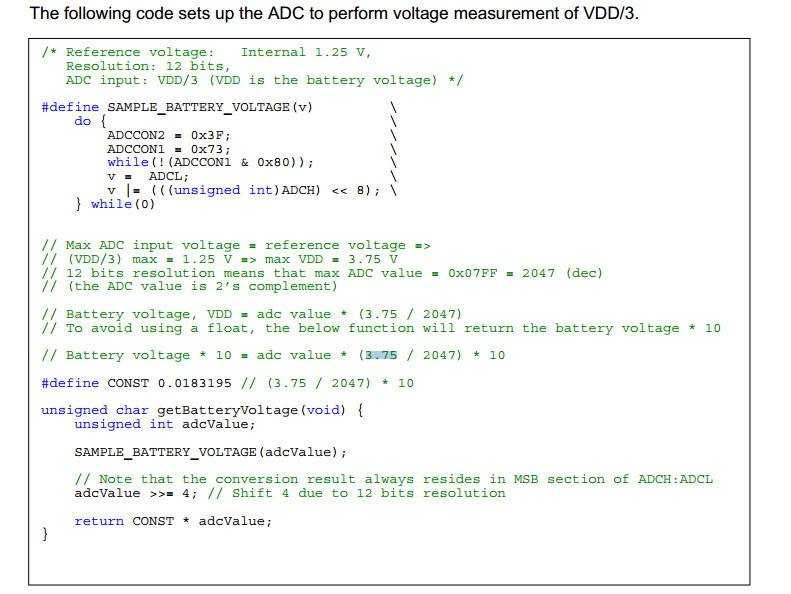
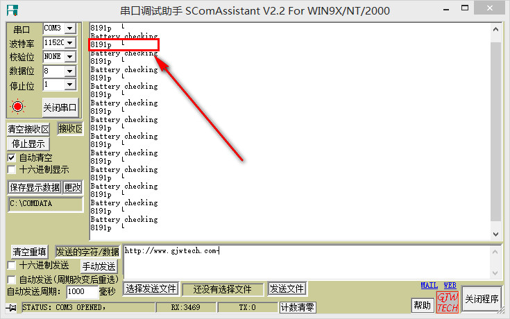
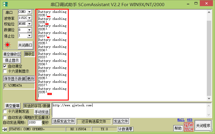
I'm now using the internal cc2530 VDD/3 to measure the voltage of battery, however, I found that I cannot get the correct value according to the adc program.
Could someone help me to see what's my problem?
I test this program both on the smartrf05eb and bb, both the readings were wrong. Thank you.
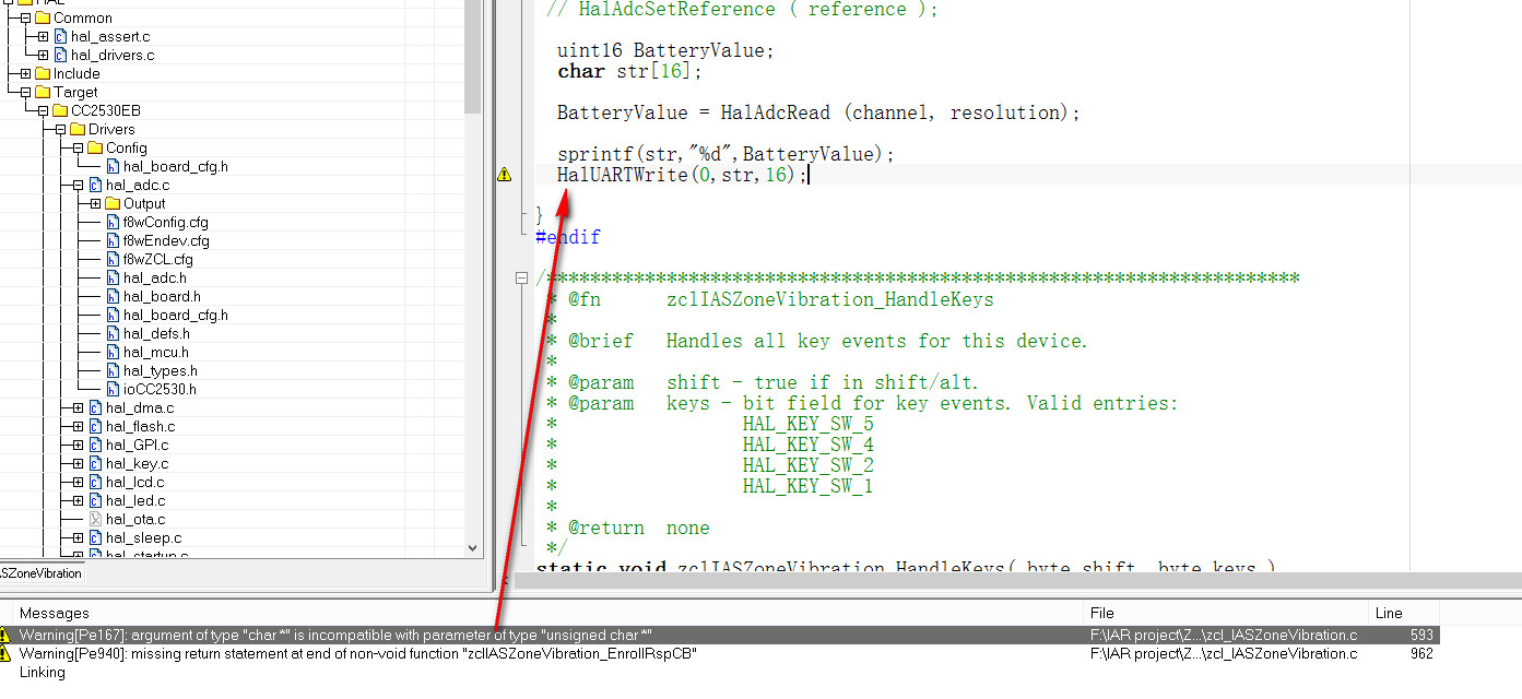
int8 HalAdcGetVdd (void)
{
ADCCON3 = 0x0F;
while (!(ADCCON1 & 0x80));
return ADCH;
}
int8 HalAdcGetTmp (void)
{
ADCCON3 = 0x0E;
while (!(ADCCON1 & 0x80));
return ADCH;
}
And By the way, according to the
Filename: hal_adc.h
Revised: $Date: 2010-03-19 20:18:21 -0700 (Fri, 19 Mar 2010) $
Revision: $Revision: 21954 $
/* Reference Voltages */
#define HAL_ADC_REF_125V 0x00 /* Internal Reference (1.25V-CC2430)(1.15V-CC2530) */
The Ref 125v in cc2530 is only about 1.15v, right? I'm looking for your reply.