


Part Number: CC2538
Hi everyone! I'm working with CC2538 as i2c master and have a problem with reading bytes from eeprom 24lc16b. This eeprom always responds 0xFF and I don't know why. There are two pull-up resistors 2.5k - on SDA and SCL pins. I attached three oscilloscopes diagrams: first is on writing byte 0x1, second - on sending eeprom address before reading (the same) and third - on reading. My code is here:
    //
    //  The I2C peripheral must be enabled before use.
    //
    SysCtrlPeripheralEnable(SYS_CTRL_PERIPH_I2C);

    //
    // Configure I2C pins
    //
    GPIODirModeSet(GPIO_I2C_BASE, PIN_I2C_SCL, GPIO_DIR_MODE_HW);
    GPIOPinTypeI2C(GPIO_I2C_BASE, PIN_I2C_SCL);
    GPIODirModeSet(GPIO_I2C_BASE, PIN_I2C_SDA, GPIO_DIR_MODE_HW);
    GPIOPinTypeI2C(GPIO_I2C_BASE, PIN_I2C_SDA);
    //
    // Configure pins as peripheral input and output
    //
    IOCPinConfigPeriphInput(GPIO_I2C_BASE, PIN_I2C_SCL,
                            IOC_I2CMSSCL);
    IOCPinConfigPeriphInput(GPIO_I2C_BASE, PIN_I2C_SDA,
                            IOC_I2CMSSDA);
    IOCPinConfigPeriphOutput(GPIO_I2C_BASE, PIN_I2C_SCL,
                             IOC_MUX_OUT_SEL_I2C_CMSSCL);
    IOCPinConfigPeriphOutput(GPIO_I2C_BASE, PIN_I2C_SDA,
                             IOC_MUX_OUT_SEL_I2C_CMSSDA);

    //
    // Enable and initialize the I2C master module.  Use the system clock for
    // the I2C module.  The last parameter sets the I2C data transfer rate.
    // If false the data rate is set to 100kbps and if true the data rate will
    // be set to 400kbps.  For this example we will use a data rate of 100kbps.
    //
    I2CMasterInitExpClk(SysCtrlClockGet(), false);

#define	I2C_ADDR_24LC16		    (0xA0UL)

    i2c_addr = (DWORD)((I2C_ADDR_24LC16 & 0xF0)>>1);

    //writing
    //eeprom address + memory block address. Last param means writing
    I2CMasterSlaveAddrSet(i2c_addr|0x1, false);
    //put a byte 0x1 to DR register
    I2CMasterDataPut(0x1);
    //send eeprom address, memory block address and a byte
    I2CMasterControl(I2C_MASTER_CMD_SINGLE_SEND);
    //wait until done
    while(I2CMasterBusy());

    //reading
    //eeprom address + memory block address. Last param means writing
    I2CMasterSlaveAddrSet(i2c_addr|0x1, false);
    //send eeprom address and memory block address
    I2CMasterControl(I2C_MASTER_CMD_SINGLE_SEND);
    //eeprom address + memory block address. Last param means reading
    I2CMasterSlaveAddrSet(i2c_addr|0x1, true);
    //send eeprom address and memory block address
    I2CMasterControl(I2C_MASTER_CMD_SINGLE_SEND);
    //read byte from DR register
    uint32_t ans = I2CMasterDataGet();
    //wait until done
    while(I2CMasterBusy());

Writing:
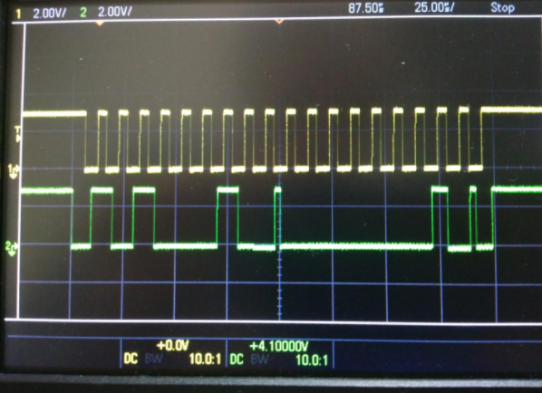
Sending address:

Reading:

Please, help somebody to solve this problem.
