This thread has been locked.

If you have a related question, please click the "Ask a related question" button in the top right corner. The newly created question will be automatically linked to this question.

CC2538: SPI flash sst26vf064ba

Part Number: CC2538

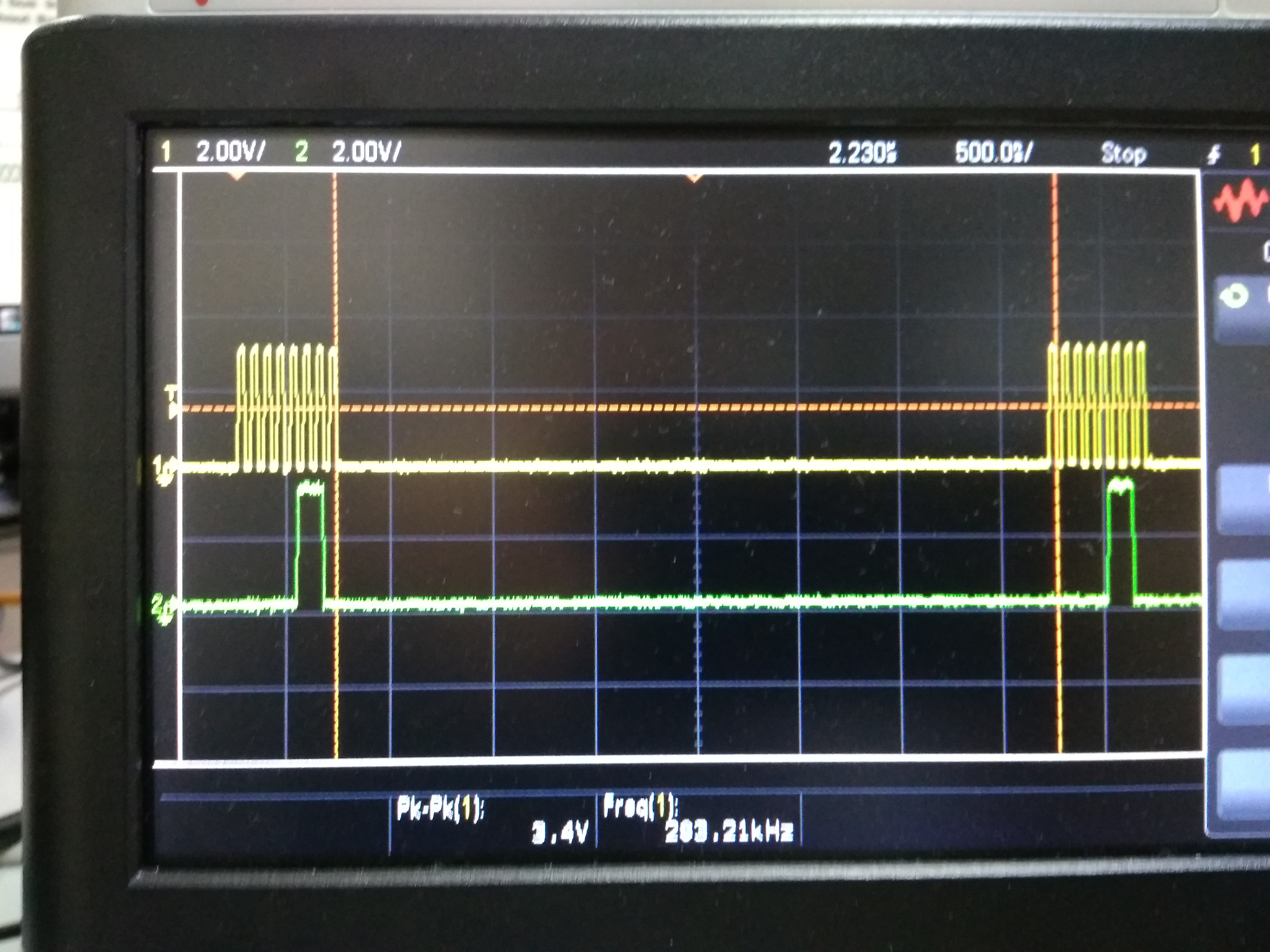
Hello! After resolving a problem with eeprom connection via I2C I'm trying to communicate with serial flash memory via SPI. I've got an example from driverlib (spi_master) and tested it on my board. It works fine when I connect MISO and MOSI together (loopback). I've tried to convert this example in order to work with spi flash sst26vf064ba but unsuccesfully. I see on my scope all needed signals (CS, CLK, MOSI) except MISO and get 0xFF or 0x0 while reading. Here is my code:

//
  // Set the clocking to run directly from the external crystal/oscillator.
  // (no ext 32k osc, no internal osc)
  //
  SysCtrlClockSet(false, false, SYS_CTRL_SYSDIV_32MHZ);
  //
  // Set IO clock to the same as system clock
  //
  SysCtrlIOClockSet(SYS_CTRL_SYSDIV_32MHZ);
  //
  // The SSI0 peripheral must be enabled for use.
  //
  SysCtrlPeripheralEnable(SYS_CTRL_PERIPH_SSI0);

  //
  // Disable SSI function before configuring module
  //
  SSIDisable(SSI0_BASE);

  //
  // Set IO clock as SSI clock source
  //
  SSIClockSourceSet(SSI0_BASE, SSI_CLOCK_PIOSC);
  
  IOCPinConfigPeriphOutput(GPIO_SSI0_BASE, PIN_SCLK0, 
                           IOC_MUX_OUT_SEL_SSI0_CLKOUT);    

  IOCPinConfigPeriphOutput(GPIO_SSI0_BASE, PIN_CS0, 
                           IOC_MUX_OUT_SEL_SSI0_FSSOUT);
  
  IOCPinConfigPeriphOutput(GPIO_SSI0_BASE, PIN_MOSI0, 
                           IOC_MUX_OUT_SEL_SSI0_TXD);    
  
  IOCPinConfigPeriphInput(GPIO_SSI0_BASE, PIN_MISO0, 
                          IOC_SSIRXD_SSI0);  
  
  GPIOPinTypeSSI(GPIO_SSI0_BASE, PIN_SCLK0 | 
                 PIN_CS0 | PIN_MISO0 | 
                 PIN_MOSI0);
  
  //
  // Configure SSI module to Motorola/Freescale SPI mode 3:
  // Polarity  = 1, SCK steady state is high
  // Phase     = 1, Data changed on first and captured on second clock edge
  // Word size = 8 bits
  //
  SSIConfigSetExpClk(SSI0_BASE, SysCtrlIOClockGet(), SSI_FRF_MOTO_MODE_0,
                     SSI_MODE_MASTER, SysCtrlClockGet()/2, 8);
  
  //
  // Enable the SSI0 module.
  //
  SSIEnable(SSI0_BASE);
  
  //
  // Read any residual data from the SSI port.  This makes sure the receive
  // FIFOs are empty, so we don't read any unwanted junk.  This is done here
  // because the SPI SSI mode is full-duplex, which allows you to send and
  // receive at the same time.  The SSIDataGetNonBlocking function returns
  // "true" when data was returned, and "false" when no data was returned.
  // The "non-blocking" function checks if there is any data in the receive
  // FIFO and does not "hang" if there isn't.
  //
  uint32_t data =0x0;
  while(SSIDataGetNonBlocking(SSI0_BASE, &data))
  {
  }
  
  int i=0;
  while(1)
  {
    /*SSIDataPut(SSI0_BASE, 0x5);
    while(SSIBusy(SSI0_BASE));    */
    while(!SSIDataPutNonBlocking(SSI0_BASE, i))
    {
    }
    /*SSIDataGet(SSI0_BASE, &data);
    while(SSIBusy(SSI0_BASE));*/
    while(SSIDataGetNonBlocking(SSI0_BASE, &data))
    {
    }
    if (data!=0xFF)
    {
      int a=0;
    }
    i = (i+1)&0xFFFFF;
  }

Does anyone know where is the problem? Please, give some advice.

  • Hello Alex,

    I assume you are sourcing from the spi_master example from the CC2538 Foundation Firmware package. Can you provide a logic analyzer or oscilloscope screenshot of your SPI lines? Have you been previously successful in communicating with the sst26vf064ba? Are you using EVMs or a custom PCB? Are you confident that your sst26vf064ba pins are properly connected?

    Regards,
    Ryan
  • Hello Ryan,

    Thanks for your answer! Yes, I'm sourcing from the spi_master example from the CC2538 Foundation Firmware package. Here is screenshots of my oscilloscope: first while sending 0x1 value and second - while sending 0x5 value. There are two lines on them - SDA and MOSI. The CS line is also good - low when the clock runs and high when not. But the MISO line is empty.

    I haven't used sst26vf064ba yet. Do you have an example with this flash memory? Or maybe with another flash like this. Pins are properly connected  - WP and HOLD on the +3VD, MOSI from CC2538 to SI on the flash, MISO - to SO, SCLK - to SCK.

    Regards,

    Alex

  • Hey Alex,

    Please refer to Section 5.3 and 5.29 of the SST26VF064BA Datasheet. You need to send a read instruction and drive the SCLK (SPI is synchronous) in order to receive bits. The write status register command (01h) will not drive the MISO line but the read status register command (05h) should produce some result so long as you follow Figure 5-29. This includes monitoring your CE# line.

    Regards,
    Ryan
  • Hey, Ryan!

    Thanks for your answer! I understood that we have to send some command to flash in order to make it set bytes on the MISO line. Now I'm trying to read JEDEC-ID (Section 5.14), but it works only on the second attempt. Could you tell me what's wrong with it? Here is my code.

      SSIConfigSetExpClk(SSI0_BASE, SysCtrlIOClockGet(), SSI_FRF_MOTO_MODE_3, 
      SSI_MODE_MASTER, SysCtrlClockGet()/16, 8);

    CE_SetLow();			 /* enable device */
        int i=0;
        int j=0;
        int k=0;
        SSIDataPut(SSI0_BASE, 0x9F);
        do
        {
          SSIDataPut(SSI0_BASE, 0xFF);   
          SSIDataGet(SSI0_BASE, (uint32_t*)Manufacturer_Id); 
          i++;
        }
        while (*Manufacturer_Id!=0xBF);
        do
        {
          SSIDataPut(SSI0_BASE, 0xFF);
          SSIDataGet(SSI0_BASE, (uint32_t*)Device_Type);
          j++;
        }
        while (*Device_Type!=0x26);
        do
        {
          SSIDataPut(SSI0_BASE, 0xFF);    
          SSIDataGet(SSI0_BASE, (uint32_t*)Device_Id);
          k++;
        }
        while (*Device_Id!=0x43);   
        CE_SetHigh();			 /* disable device */

    The result is correct, but the first counter i=2. It means that when we read first time the result is 0xFF and on the second time - 0xBF. Values of counters j=k=1.

  • Hey Alex,

    There is probably not enough time between the 0x9F and buffer (0xFF) SSIDataPut commands. Insert a delay or wait until the SPI buffer is empty before sending the buffer. Please continue using an oscilloscope to view the data lines.

    Regards,
    Ryan