This thread has been locked.

If you have a related question, please click the "Ask a related question" button in the top right corner. The newly created question will be automatically linked to this question.

CC2530: Zigbee Module Transmitting & Receiving Power and Range is very poor

Part Number: CC2530
Other Parts Discussed in Thread: Z-STACK, , CC2591, CC2592

Dear All,

We are using Fietbit module based on CC2530 chip and using TI Z-Stack 3.0.0. The feitbit module is PA based.

During development and integration, we are facing an issue with the module RF signal transmitting and receiving power and range is very very less.

We enabled the macro #define HAL_PA_LNA

While trying to join the zigbee devices (sensors), the joining process starts within close distance of 8 cms and beyond this range, joining process never starts.

Also, the joining process never completes successfully as the device leaves the joining process unexpectedly.

Please find attached log for the above issue.1614.Capture.zip

Regards,

Sanjay

  • If you use HAP_PA_LNA, you have to make sure your module use CC2591 and connection between CC2530 and CC2591 is the same to www.ti.com/.../swra308a.pdf . Otherwise, you will have range problem since SW settings is not matching to your HW.
  • Thanks for quick response,

    Yes, Module have a connection with cc2530 and CC2592. Can you help in change configuration for Z-stack 3.0.0
  • If the module use cC2592, you should refer to www.ti.com/.../swra465a.pdf . If the connection between CC2530 and CC2592 on your module is the same to application note, you only have to define HAL_PA_LNA_CC2592 instead of HAL_PA_LNA.
  • After change HAL_PA_LNA to HAL_PA_LAN_CC2592 result is same and CC2530 register recommended value also same.
    Please guide how to solve this issue
  • I set both option HAL_PA_LNA_CC2592 and ZMacSetTransmitPower(TX_PWR_PLUS_19) , function also return ZMacSuccess .
    Problem still exits.
  • Can you please post your schematics so that we can see how you have connected the CC2592 and CC2530?
  • Without checking schematic of your module, I cannot judge anything.
  • Please find Feibit module schematic document
  • I think you should check it by yourself.
  • 7802.FZB57A5+原理图.pdfPlease find feibit schematics document

  • Please suggest which point check in SW module
  • The schematic is the same to reference design so you only have to define HAL_PA_LNA_CC2592 in your project to make it work.
  • It is possible problem in Antenna, I set different value using ZMacSetTransmitPower() function , RSSI value increase and decrease ,but no difference in range
  • Maybe. I suggest you to use Flash Programmer 2 to do PER test first.
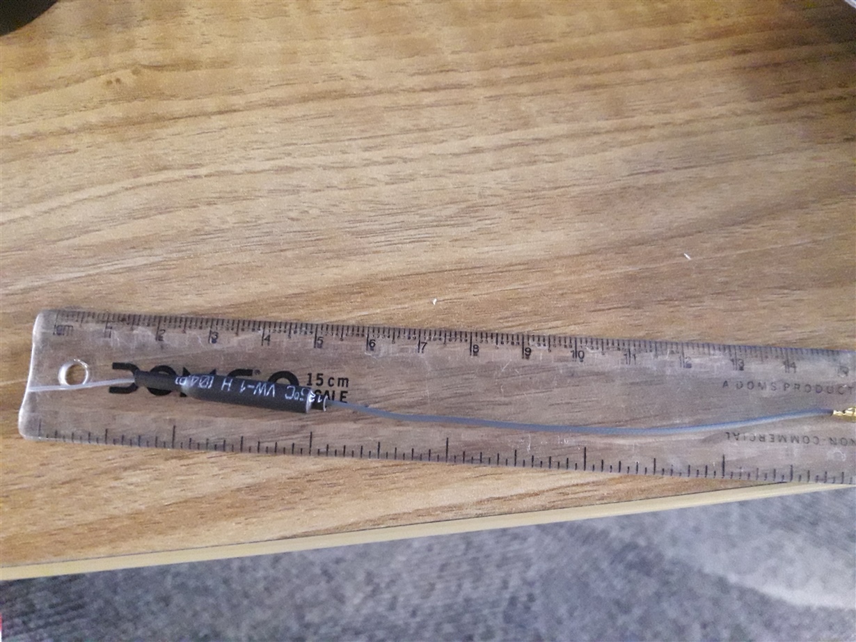
  •  Can you verify  antenna , I have attached picture, it's 15 cm long

  • I cannot verify antenna by a picture.
  • Yes, the schematic is all connected properly it appears. I would imagine it is probably something to do with the antenna, however, I cannot confirm from the picture.

    Please try to do a PER test via something like SmartRF Studio with the range being further away than what you were using Z-Stack application and report back with results.
  • Uart not working properly,
    scenery is, endpoint registration completed, after that write command for permit join , response receive proper data, but after receive junk data, each data convert into 0xFD. starting byte should be 0xFE but receive all bytes 0xFD 0xFD 0xFD ....

    I think my uart Suspend and resume function not working.


    My modify code is.

    #define HAL_UART_DMA 2
    #define HAL_UART_PORT 1

    static void HalUARTInitDMA(void)
    {
    halDMADesc_t *ch;

    P2DIR &= ~P2DIR_PRIPO;
    P2DIR |= HAL_UART_PRIPO;

    #if (HAL_UART_DMA == 1)
    PERCFG &= ~HAL_UART_PERCFG_BIT; // Set UART0 I/O to Alt. 1 location on P0.
    #else
    PERCFG |= HAL_UART_PERCFG_BIT; // Set UART1 I/O to Alt. 2 location on P1.
    #endif
    PxSEL |= HAL_UART_Px_RX_TX; // Enable Tx and Rx on P1.
    // Configure relevant Port P0 pins back to GPIO function
    P0SEL &= ~0x3C;
    ADCCFG &= ~HAL_UART_Px_RX_TX; // Make sure ADC doesnt use this.
    UxCSR = CSR_MODE; // Mode is UART Mode.
    //UxUCR = UCR_FLUSH; // Flush it.
    UxUCR |= 0x00; //

    .........


    void InitBoard( uint8 level )
    {
    if ( level == OB_COLD )
    {
    // IAR does not zero-out this byte below the XSTACK.
    *(uint8 *)0x0 = 0;
    // Interrupts off
    osal_int_disable( INTS_ALL );
    // Check for Brown-Out reset
    ChkReset();

    #if defined CC2531ZNP
    znpCfg1 = ZNP_CFG1_UART;
    #elif defined CC2530_MK
    znpCfg1 = ZNP_CFG1_SPI;
    znpCfg0 = ZNP_CFG0_32K_OSC;
    #else znpCfg1 = ZNP_CFG1_UART;
    znpCfg0 = /*ZNP_CFG0_32K_OSC */ ZNP_CFG0_32K_XTAL;
    //znpCfg1 = P2_0;
    //znpCfg0 = P1_2;
    // Tri-state the 2 CFG inputs after being read (see hal_board_cfg_xxx.h for CFG0.)
    //P1INP |= BV(2);
    //P2INP |= BV(0);
    #endif
  • I suggest you to connect your CC2530 to desktop and use ZTool to verify your ZNP FW first.
  •      
    /****************************************************************************
    * �� �� ��: main.c
    * ��    ��: Andy
    * ��    ��: 2013-01-08
    * ��    ��: 1.0
    * ��    ��: ���ô��ڵ������ֲ����ʣ�115200bps 8N1
    *           ���ڵ������ָ�CC2530���ַ���ʱ��������᷵�ؽ��յ����ַ���
    ****************************************************************************/
    #include <ioCC2530.h>
    #include <string.h>
    #include <stdio.h>


    //..............................................................................
    void initUART(void) //sets all configurations in UART
    {
            CLKCONCMD = CLKCONSTA & 0xB8; //clock control
           //CLKCONCMD &= ~0x40;                        //����ϵͳʱ��ԴΪ32MHZ����
     
           while(CLKCONSTA & 0x40);                   //�ȴ������ȶ�Ϊ32M
            CLKCONCMD &= ~0x47;                        //����ϵͳ��ʱ��Ƶ��Ϊ32MHZ   
    
     // CLKCONCMD = CLKCONSTA & 0xB8; //clock control
    //   while(CLKCONSTA & 0x40); 
    
    
       PERCFG |= 0x02; // Configure UART1 for Alternative 2 => Port P1 (PERCFG.U1CFG = 1)
    
    // P1SEL.SELP1_4/5/6/7 = 1 => CT = P1_4, RT = P1_5, TX = P1_6, RX = P1_7 
       P1SEL |= 0xF0;
    // Configure relevant Port P0 pins back to GPIO function 
       P0SEL &= ~0x3C;
    
       U1CSR |= 0x80; // USART mode = UART (U1CSR.MODE = 1) 
       U1CSR |= 0x40;//0xC0; //UART mode selected for USART1.
       //U1UCR |= 0x00; //H/w flow control disabled
    
       U1GCR = 8;	//for 9600			       
       U1BAUD = 0x3B;           //9600
     // DMA Rx is always on (self-resetting). So flow must be controlled by the S/W polling the Rx
     // buffer level. Start by allowing flow.
    #if 0
        P1 &= ~0x20;//HAL_UART_Px_RTS;
        P1DIR |=  0x20;//HAL_UART_Px_RTS;
    // Trigger an interrupt on CTS input (enabled in HalUARTSuspendDMA).
        P1IFG &= ~0x10;
        P1IEN &= ~0x10;
        P0IE = 1;
    #endif
    
    }
    //..............................................................................
    char receive (void) 
    {
         U1CSR |= 0x40;
         URX1IF = 0;      //interrupt flag
         while (!URX1IF ); 
             U1DBUF; //USART 0 Receive/Transmit Data Buffer
         URX1IF = 0;
    return U1DBUF;
    }
    //..............................................................................
    void send(unsigned char c) 
    { 
         UTX1IF = 0; 
         U1DBUF = c; 
         while (!UTX1IF); 
             UTX1IF = 0; 
    }
    //..............................................................................
    void main()
    { 
           int i=0;
           initUART(); 
           
    
           while(1)
           {
              unsigned char uartdat;


              for (i=0;i<10;i++){
                 uartdat='2';
                 send(uartdat);
              }
    
              for (i=0;i<10;i++)
              uartdat=receive();
             
           }
    }
    
    UART Communication issue.
                    In following scenario working:-
                            firmware receive command and send response of command.
                            firmware  <----------- UART(Host)
                            firmware  ----------->UART(Host)
                    In following scenario not working  (sending junk data)
                    if firmware side receive any notification and send to UART then only send 0xFD
                     firmware -------------> UART(Host)
                     (Data is 0xFD,...)
     
    UART read/write working fine. change to write/read not working, UART host application receive 0xFD value.
      And data missing also. 
      I have attached my UART code, please check.
     Working code is
                                for (i=0;i<10;i++)
                                    uartdat=receive();
                              for (i=0;i<10;i++){
                                   uartdat='2';
                                   send(uartdat);
                              }

             Nott working, host receive 0xFD:-

                            for (i=0;i<10;i++){

                                   uartdat='2';
                                   send(uartdat);
                              }
                            for (i=0;i<10;i++)
                                    uartdat=receive();
  • Please check log, first time receive 0xFD value and later send receive working properly.
    any flag required to set before send data.

    0xfd 0xfd 0xfd
    0xfd 0xfd 0xfd 0xfd 0xfd 0xfd 0xfd 0xfd 0xfd 0xfd 0xfd 0xfd 0xfd 0xfd 0xfd 0xfd
    0x32 0x32 0x32 0x32 0x32 0x32 0x32 0x32 0x32 0x32
    0x32 0x32 0x32 0x32 0x32 0x32 0x32 0x32 0x32 0x32
    0x32 0x32 0x32 0x32 0x32 0x32 0x32 0x32 0x32 0x32
    0x32 0x32 0x32 0x32 0x32 0x32 0x32 0x32 0x32 0x32
    0x32 0x32 0x32 0x32 0x32 0x32 0x32 0x32 0x32 0x32
    0x32 0x32 0x32 0x32 0x32 0x32 0x32 0x32 0x32 0x32
    0x32 0x32 0x32 0x32 0x32 0x32 0x32 0x32 0x32 0x32
    0x32 0x32 0x32 0x32 0x32 0x32 0x32 0x32 0x32 0x32
    0x32 0x32 0x32 0x32 0x32 0x32 0x32 0x32 0x32 0x32
    0x32 0x32 0x32 0x32 0x32 0x32 0x32 0x32 0x32 0x32
    0x32 0x32 0x32 0x32 0x32 0x32 0x32 0x32 0x32 0x32
    0x32 0x32 0x32 0x32 0x32 0x32 0x32 0x32 0x32 0x32
    0x32 0x32 0x32 0x32 0x32 0x32 0x32 0x32 0x32 0x32
    0x32 0x32 0x32 0x32 0x32 0x32 0x32 0x32 0x32 0x32
    0x32 0x32 0x32 0x32 0x32 0x32 0x32 0x32 0x32 0x32
    0x32 0x32 0x32 0x32 0x32 0x32 0x32 0x32 0x32 0x32
    0x32 0x32 0x32 0x32 0x32 0x32 0x32 0x32 0x32 0x32
    0x32 0x32 0x32 0x32 0x32 0x32 0x32 0x32 0x32 0x32
    0x32 0x32 0x32 0x32 0x32 0x32 0x32 0x32 0x32 0x32
  • I couldn't understand what you describe. Can you elaborate your problem/question?
  • We are writing UART code and the objective of this is to send continuously data over UART to the Host (UART Receiver, linux based).
    During this process we observed that the receiver receives wrong data and the data is 0xfd.


    On further debugging, we understood that when linux UART sends the data to firmware (UART Code), firmware receives and sends response with proper data in case of there is no wait or delay for response.

    But if we insert delay or wait between receiving and sending, the wrong data is being sent.

    If code written is only for sending UART data continuously, incorrect data is sent.

    Please check the below code for sending continuous data with delay. The output of this code is wrong data, 0xfd being sent in response.

    Same code without delay, the first 10 bytes is wrong and then the following data is proper.

    Log attached in the above reply.


    void send(unsigned char c)
    {
    UTX1IF = 0;
    U1DBUF = c;
    while (!UTX1IF);
    UTX1IF = 0;
    }
    //..............................................................................
    void main()
    {
    int i=0;
    unsigned int usec;
    initUART();


    while(1)
    {
    unsigned char uartdat;
    for (i=0;i<10;i++){
    uartdat='2';
    send(uartdat);
    }
    uartdat=receive();

    usec = 0xFFFFFF;
    while(usec--)
    {
    asm ("nop");;
    asm ("nop");
    asm ("nop");
    asm ("nop");;
    asm ("nop");
    asm ("nop");
    asm ("nop");;
    asm ("nop");
    asm ("nop");
    asm ("nop");;
    asm ("nop");
    asm ("nop");
    asm ("nop");;
    asm ("nop");
    asm ("nop");

    }

    }
    }
  • I see that you are working to resolve your UART issue on the E2E post here: e2e.ti.com/.../

    I would recommend continue working on it on that thread, so as to avoid confusion moving back and forth between multiple threads.

    Best,
    Sean
  • Yes, I found UART communication issue also in module and working on that, I checked with different antenna as well another module, but result is same, I will check low signal issue after solve UART issue.
  • Hi Sean/chen,

    I solved UART issue as well PA enable issue, know zigbee working fine.
    Thanks for your support.