


Other Parts Discussed in Thread: CC2650, CC2592
We are considering CC2652R for our upcoming products. However we need a PA LNA for a better range. Launchpad design doesn't include any PA LNA. Some online research revealed that I can use the reference design of CC2650+2592 as shown below:
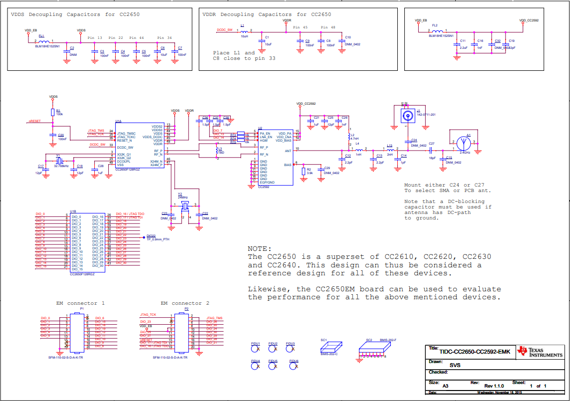
Q1 - Can I copy this design for the RF part starting from RF_P and RF_N pins?
Q2 - For cc2650+2592, PA_EN, LNA_EN and HGM pins are connected to DIO 7, 13 and 14 respectively. Where should I connect those pins in case of CC2652r?
Q3 - There is a RF matching network between ANT pin of cc2592 and the antenna. It comprises of 5-6 components. Is it advisable to replace these components with a single balun component (ease of implementation is the major concern. other concerns are performance > cost > PCB area requirement)? If a balun component is advisable, which part number should I go with?
Q4 - How many copper layers should I use for best performance and passing compliance tests? What should be the stackup and thickness of copper and FR4 layers?
