This thread has been locked.

If you have a related question, please click the "Ask a related question" button in the top right corner. The newly created question will be automatically linked to this question.

LAUNCHXL-CC1352P: Debug connection error

Part Number: LAUNCHXL-CC1352P
Other Parts Discussed in Thread: CC1352P, SEGGER, CC2640, CC2640R2F

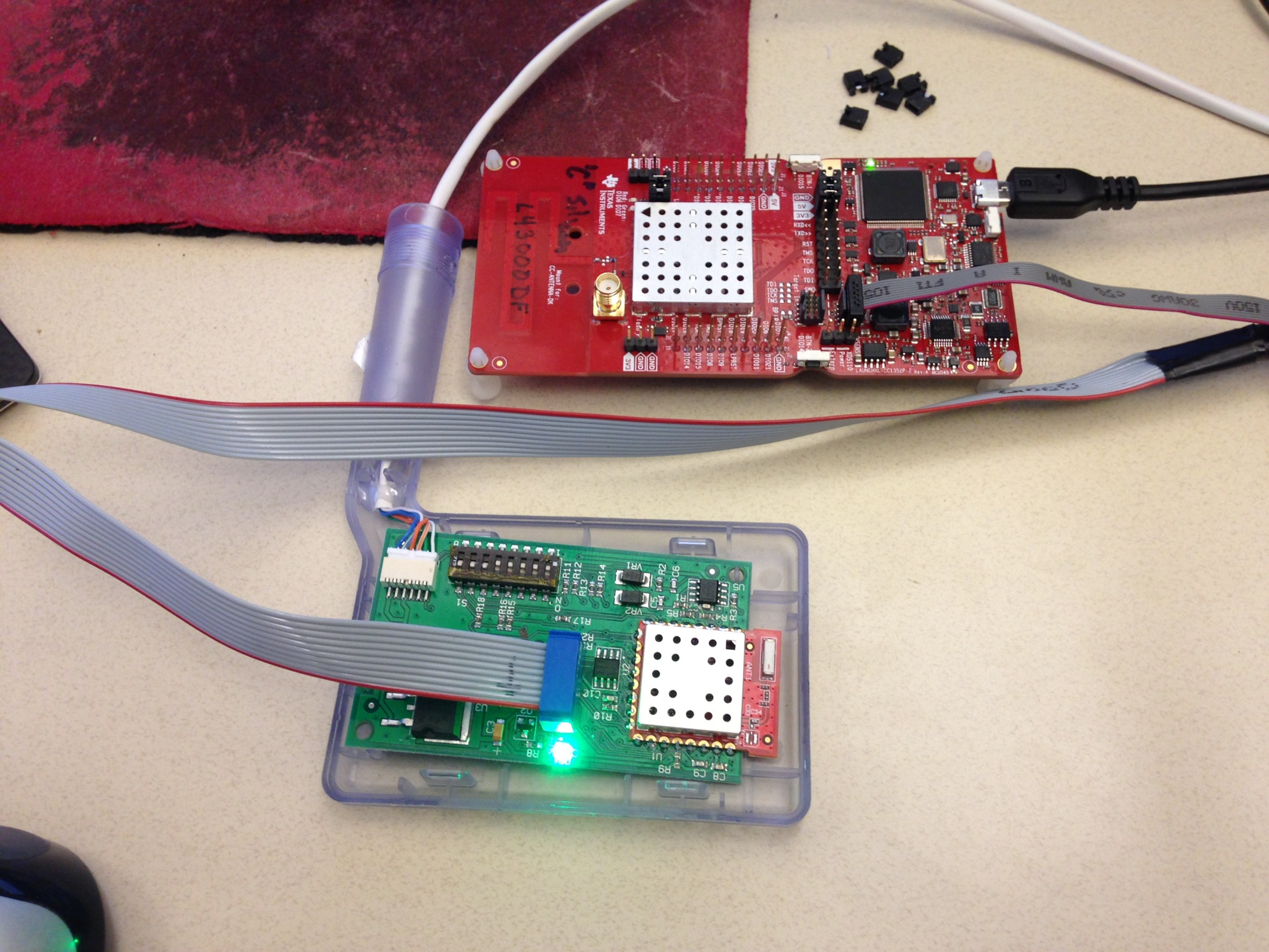
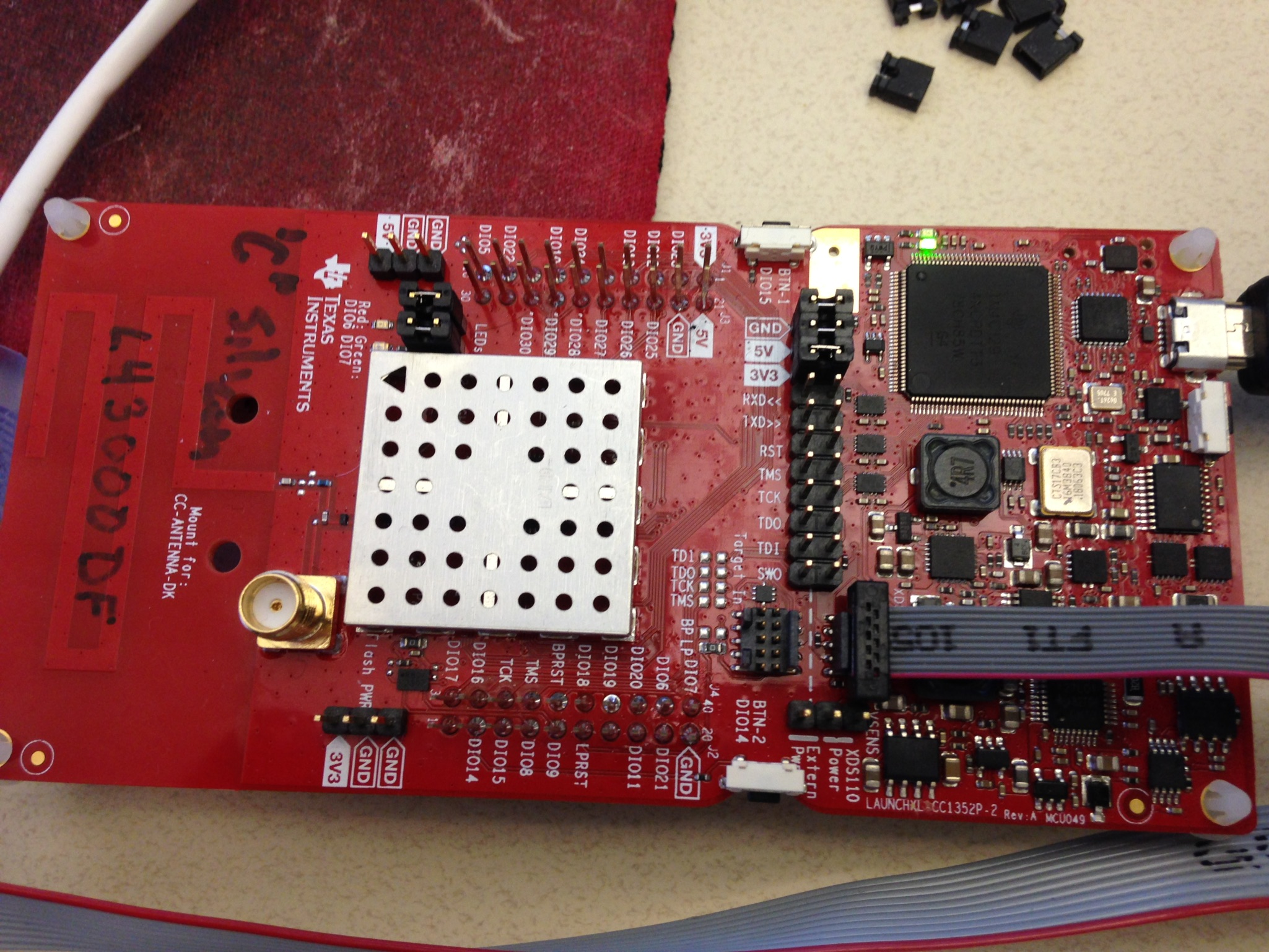
I'm trying to connect the XDS110 side of the launchpad to my target.  I've removed all of the jumpers between the XDS110 and the on-board CC1352P and run a ribbon cable from the XDS110 side to my target. I've also removed the power jumper because I power my target externally.

When I use a Segger j-link to my target, it works fine, but I'm unable to configure j-link to clear all flash memory in the Debug settings. That's why I would like to try the XDS110.

When the debug session starts, I get this error:

Error connecting to the target:
(Error -2131 @ 0x0)
Unable to access device register. Reset the device, and retry the operation. If error persists, confirm configuration, power-cycle the board, and/or try more reliable JTAG settings (e.g. lower TCLK).

My target is built with the Rev:E silicon and I'm using the 2.40sdk.

Any help would be appreciated.

Thanks,

- Bill

  • Can Flash Programmer 2 detect your CC1352P?
  • I was able to connect with the Flash Programmer 2, but only if I remove the external power and add the jumper to power the device from the XDS110.

    I went back to CCS and now I get a different but similar error...

    Error connecting to the target:

    (Error -1170 @ 0x0)
    Unable to access the DAP. Reset the device, and retry the operation. If error persists, confirm configuration, power-cycle the board, and/or try more reliable JTAG settings (e.g. lower TCLK).
    (Emulation package 8.0.903.6)
  • Can you take a picture to show me your connection?
  • We had to make a custom cable to go from the 10 pin jtag header to our legacy 10 pin header.  Its mapped out as follows:

    1352P Usage Chip Pin Legacy Debug Header 10 pin
    ARM-JTAG Header
    Ground PAD 1 3, 5, 9
    JTAG_TDO 26 2 6
    JTAG_TDI 27 9 8
    SPI_SSN 30 3  
    SPI_SCK 16 8  
    MCU_RESET# 35 4 10
    JTAG_TCK   7 4
    JTAG_TMS   6 2
    VDDS (via L13) 44 5, 10 1

    Thanks,

    - Bill

  • Try to use a shorter ribbon cable which is less than 10 cm.
  • I shortened the cable and still get the same error. 

    Again, seems to work OK from "Flash Programmer 2" but not when I try to use it as a debugger interface from CCS.

    Also does not work from UniFlash-4.5.0.  It first tells me:

    device is locked

    - Bill

  • Try to use Flash Programmer 2 to do mass erase to test again.
  • Doing the mass erase seemed to work.  But only if I power the target from the XDS110.  ie I need to remove power from my target and place a jumper as shown below.

    This is a problem because I need to power the whole target, not just the processor.

    If I have the jumper in place and apply power to the target, it does not work. I get the same error as above.

    Error connecting to the target:
    (Error -2131 @ 0x0)
    Unable to access device register. Reset the device, and retry the operation. If error persists, confirm configuration, power-cycle the board, and/or try more reliable JTAG settings (e.g. lower TCLK).

    If I disconnect external power, start the debugger and then apply power, then the debugger works.

    So it seems to be having a problem only in downloading the image with external power connected to the target.

    Vcc at the processor is the same whether powered only from the XDS110 or only external.

    Are there some signals that I should be monitoring with a scope? What should I be looking for?

    - Bill

  • Hi,
    Quoting the general procedure from the link below. Even though the device is CC2640, the debuggers are the same and the procedure should apply to CC1352 launchpad.
    dev.ti.com/.../landing_page_index.html

    "The onboard XDS110 can be used to debug external targets, and it is possible to use external debuggers with the onboard CC2640R2F. In either case, all the jumpers on the jumper block must be removed.

    With all the jumper block jumpers removed, the XDS110 Out header will work as debug output for the XDS110, and the Target In header will work as debug connector for the CC2640R2F. The XDS110 output is level shifted and support target voltages between 1.8 V and 3.6 V. If the target board is powered externally, the VSENSE jumper must removed. Alternatively, the target can be powered by the LaunchPad through the debug header (connecting the Vsense pin to the LaunchPad 3.3 V supply), in this case the VSENSE jumper must be placed in the XDS110 Power position (the default position)."
  • "If the target board is powered externally, the VSENSE jumper must removed."

    This is how I'm trying to use the Launchpad XDS and it is not working. It will only work if the VSENSE jumper is in the XDS110 Power Position and I remove the external power from my target.
  • I suppose you can remove VSENSE jumper when you use external power for your target and you should also remove GND/5V/3V3 jumpers between XDS110 and CC1352P on LaunchPad.
  • Hi,
    Were you able to resolve this issue?
    I have tried debugging and programming a sensor tag with launchpad which worked fine when externally powered or powered by VSENSE. Can you verify that your schematic follows the JTAG connectivity and power supply according to this design www.ti.com/.../swrc321.
  • We did find an issue in that we had a 1k series resistor between the TCK pin on the RF module and the jtag header located on the host board.  Shorting this resistor seemed to help.  

    I noticed on the reference schematic that you were also running the TDI/TDO signals from the processor to the jtag header.  Are these necessary, or does the debugger work with just TCK/TMS/RESET?

  • Hi,
    If you are using 4-pin JTAG then TDI/TDO are necessary otherwise only TMS/TCK/RESET (cJTAG) are sufficient. The default configuration after power up is 2-pin mode.
  • Thanks.