This thread has been locked.

If you have a related question, please click the "Ask a related question" button in the top right corner. The newly created question will be automatically linked to this question.

CC2530: How to pass ETSI EN 300328 RF test when output power is greater than 10dBm?

Part Number: CC2530

Hi,

How to pass ETSI EN 300328 RF test when output power is greater than 10dBm?

My customer add a external PA with CC2530 and set output power up to 20dBm.

During the added activity test, unable to communicate in the same channel after add awgn interference signal.

Is there any advice here? Thanks.

  • Hi,

    For Q1 - They have 2 options. They can use Frequency Hopping or Wideband Modulation. In both cases , the maximum EIRP allowed is +20dBm. Yes, other conditions apply. Please refer to the standard for further details. The following is the link to the Standard. It is very detailed.

    The EN 300 328 specification can be found here: https://www.etsi.org/deliver/etsi_en/300300_300399/300328/02.01.01_60/en_300328v020101p.pdf

    I don't understand the 2nd question. Could you please elaborate?

    Thanks,

    PM

  • Hi PM,

    About the 2nd question.

    When TX output power is greater than 10dbm, CE require it must pass addition activity test.

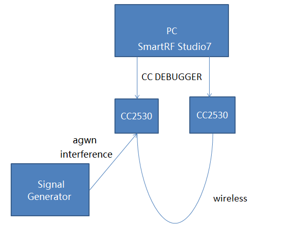
    As below picture, inject a agwn interference signal to the working channel, CC2530 will be interrupted and stop working, result in failed to pass test.

  • Hi,

    CCA - Tx should monitor it's own channel (intends to transmit on that channel) before it transmits. If the channel is busy ( that means if the measured RSSI is greater than the Threshold level for example -70dBm) then the Tx should not transmit. If the channel is free (that means if the measured RSSI is Less than the Threshold level for example -70dBm) then it can transmit.

    They can do it in the following steps.

    1. Better to add an Attenuator (30dB) in between both Tx and Rx devices (CC2530). This helps in isolating the Receiver from the AWGN signal.
    2. Set the Tx power to -10dBm or higher
    3. Test the Link ( PER test)
    4. Add AWGN (in the channel being used) to the Transmit device (CC2530)
    5. Set the AWGN level to a little higher than the Threshold limit (>-70dBm)
    6. You can measure the RSSI at Transmitter and Receiver to make sure your setup and levels are correct.
    7. If everything correct then you should see RSSI at the Transmitter is >-70dBm and around -100dBm (because of Attenuator Loss 30dB) at the Receiver.
    8. Start the Link ( PER test)
    9. The Transmitter should not transmit in this condition because it sees the signal is present in the channel and it is greater than the Threshold level.
    10. Then reduce the AWGN level to <-75dBm
    11. Start the Link (PER test)
    12. Now the Link should work without any issue.

    Also please refer to section 5.4.6 in the standard EN_300328 for a detailed test procedure and a test setup.

    Thanks,

    PM