This thread has been locked.

If you have a related question, please click the "Ask a related question" button in the top right corner. The newly created question will be automatically linked to this question.

CC2538: Light-Level dependend power consumption with connected LEDs

Part Number: CC2538


Hello,

I'm trying to optimize for power consumption using ZStack on an otherwise perfectly working custom CC2538 board.

The device  has right now an average of 300uA@3V consumption and ~120uA in PM2

While trying to optimize an off-mode for a few more uA savings i noticed different readings on the currents drawn:

Whenever the light in my office was turned on, the consumption was a few uA higher. Testing each component on the board by shielding it from the light I notized this raisecomes from the ollowing LEDs:

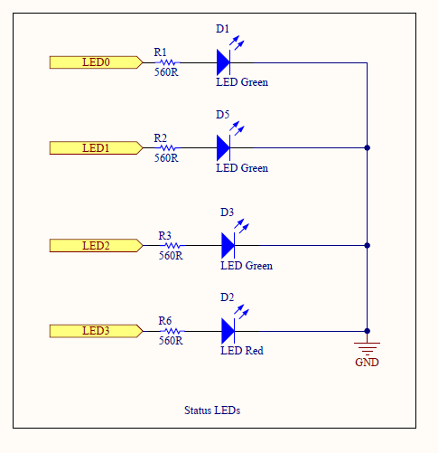
The pin's configuration registers are 0 and their direction is set to input. So that they should be input pins without pull-up or -down and no sampling. So basically the pins should be floating on the CC2538 side.

When I have this board running in pitch-black dark in PM2, I have a power consumption of ~18uA  (Measured with an HP34401A @ 3.0V Supply). In the office with blinds down and light on, this raises to 120-125uA

With a LED Flashlight pointed to the LEDs, this raises further to 350uA.

I understand that the LEDs are subject to the photoeffect and generates a voltage (measured directly at the LED, i was able to read ~+1.5V facing the CC2538), which might cause a current through the series resistors and the IO Pin. On the other hand, there is a RTC running with an IRQ line connected to PB2, which is constantly at 3.3V (VCC) and does not seem to generate any current/loss.

Is there a way to prevent the current through the IO Pin to fight this loss?

What could cause this effect?

Thanks in advance.

With kind regards,

Tim Seidel

  • Hi Tim,

    Is there a reason you have them set as inputs? Setting them as outputs would probably solve your problem, but if you really need them configured as inputs for your application, maybe try setting them as high-impedance inputs.

    Thanks,
    Alexis
  • Hello Alexis,

    That was my first naive approach to the LEDs, however I found that setting them as input reduced the overall power consumption.

    The device original used about 1350uA on average on essentially the same hardware. I took the following steps:

    • The clock was changed to run a hybrid  (8MHz when checking between single PM2 calls and 2MHz while running the tasks), saving me about 100uA average
    • An external TWI pullup was removed and the internal TWI pull ups are removed (carefully avoiding Start-Conditions) when no measurements are taken, saving about 300uA (there is a sensor, that draws power out of TWI lines, if its internal regulator was turned off to save some more uA while it was not needed to operate)
    • Another sensor was shut down into a deeper sleep, saving another 250uA on average.

    So that left me with about 600uA letting me run the device for about 20weeks on two AA batteries, which I was trying to get above 52 weeks.

    Since the numbers were nowhere near the 1.5uA vor PM2 + sensor consumption I tested several things to disable within the CC2538, which did not have much more running. To Do so I c&p-ed the halSleep routine to set the device into PM2 once all sensors were initialized and sleeping. Since I had to clear the LEDs and other pins, I just wrote the config for the whole ports. That took me down to about 120uA. sometimes more and sometimes less.

    Leaving them as output-low raises my power consumption, when nothing else changed, so I kept them at input and actually changed my LED control to output_high/high-z instead of push-pull.

    So the current state as input is already (even with that curious light effect) is much lower then having them as output.

    I think I can get around this issue, by replacing the R->LED with a R->D->LED path and by enabling the pull-downs again. This should get rid of the voltage offset at the IO pins and keep a consumption <50uA in PM2. But I am really curious for the reason to this. I am a software developer and my knowledge on the electronics is not that deep as an electrical engineer.

    My current imagination is that the input buffer, while not drawing actually from the pin is getting nearer to the switching point and the fets inside an internal push-pull might already slowly get out of the off-state and thus generating a leakage.

    It just seemed odd. And I'd like to understand. Esp. since the effect whaile beeing small is multiple times my PM2 consumption.

  • Hi Tim,

    With your current implementation of the GPIOs configured as inputs, the LEDs are basically acting like photodiodes (which convert light into an electrical current).

    Thanks,
    Alexis