This thread has been locked.

If you have a related question, please click the "Ask a related question" button in the top right corner. The newly created question will be automatically linked to this question.

LAUNCHXL-CC1352P: ADC input scanning gets stuck in Sensor Controller Studio

Part Number: LAUNCHXL-CC1352P

I have a CC1352P-2 LaunchPad, Simplelink_cc13x2_26x2_sdk version 3.20.0.68, Sensor Controller Studio 2.5.0.84. 

I need to sample 3 ADC channels nearly simultaneously, by taking a sample on channel 1, then switch to channel 2, then channel 3 then go back to channel 1 and so on. So I started with the ADC Data Streamer example, which samples a single channel over and over, and altered it to sample 3 channels instead.

However when I run it, it always gets stuck in the adcReadFifo() function. Can anyone help with this? It seems like I should be able to switch pins on each loop iteration, but it gets stuck.

Thanks,

Tim

PS Where is the best forum to post on Sensor Controller Studio? I posted in the Zigbee forum because I'm creating a Zigbee project.

  • Hi Tim,

    I think your problem is exactly the same as the one described and solved in the following thread:https://e2e.ti.com/support/wireless-connectivity/bluetooth/f/538/t/690179

    I hope this will help,

    Regards,

  • He Clément,

    I look at that link but it didn't solve my problem. That link samples the same pin over and over, they call adcSelectGpioInput(AUXIO_A_SENSOR_OUTPUT) and never select a different input.

    But I;m selecting a different pin with each loop iteration (cfg.pAuxioAAdcInput[] is an array of pin numbers)

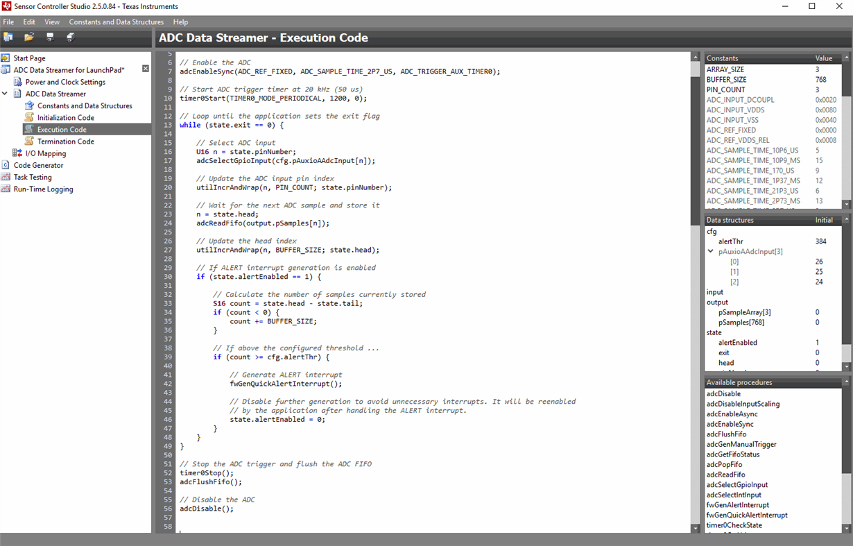
      // Select ADC input

      U16 n = state.pinNumber;

      adcSelectGpioInput(cfg.pAuxioAAdcInput[n]);

    So there's something about changing the input pin to the ADC that is messing things up. Or maybe it's fact that I'm driving the ADC conversion with a timer, instead of manually triggering the ADC?

    Other people must be changing the ADC input pin and then sampling. I can't believe everyone samples just a single pin.

    Any help you can give in solving this will be appreciated.

    Thanks,

    Tim

  • Hi Tim,

    Can you verify if your IO mapping is correct? (no pin conflict, each ADC pin properly declared...)

    Can you also verify if you can run the example (with only one ADC) with each one of the pin/channels you are trying to use? Same question trying to run the example adding the timer. This will help me to identify the problem.

    Regards,

  • He Clément,

    I ran the tests you suggested. Here are the test descriptions and the results.

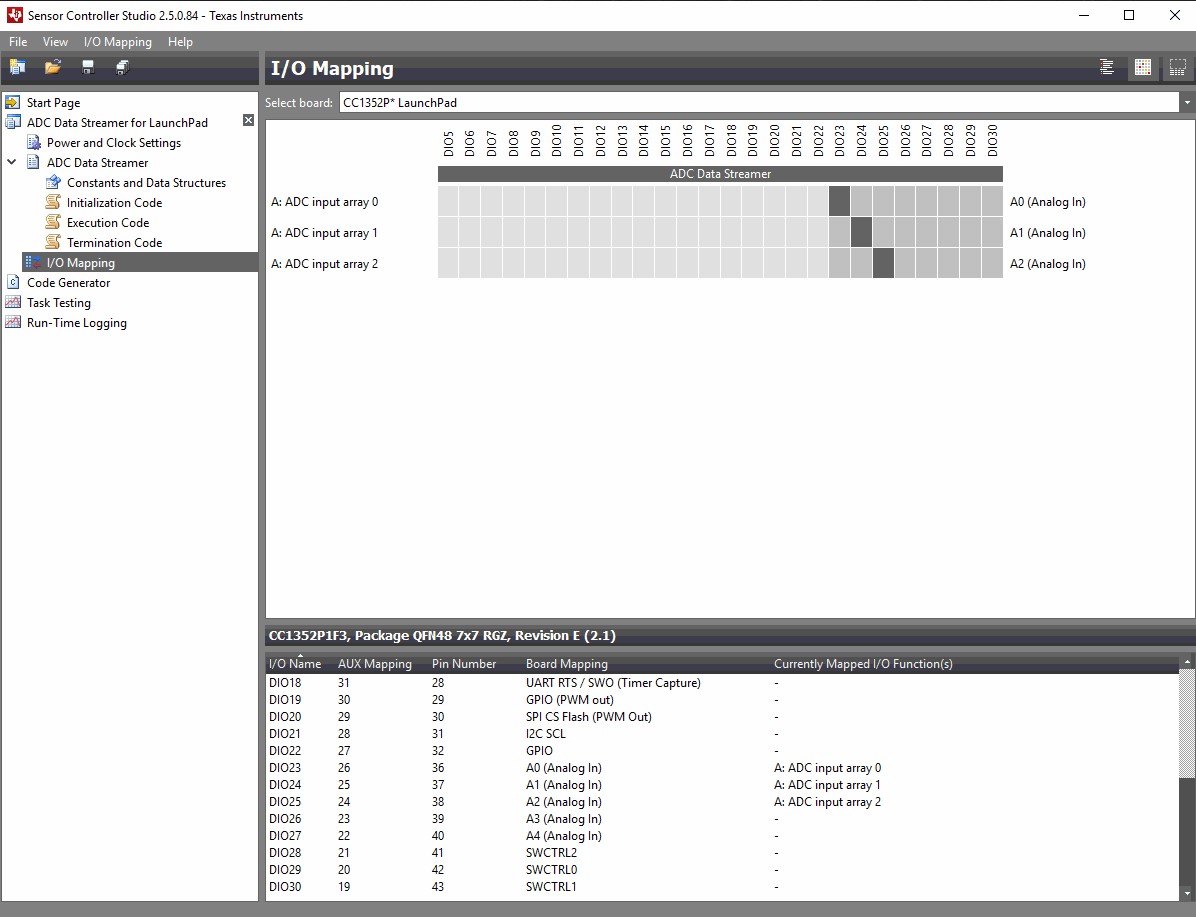
    I think I have the i/o mapping right, I'm using DIO23, DIO24 and DIO25 (see screenshot). I have these three pins defined in an array cfg.pAuxioAAdcInput[].

    I ran the following code three times, using the values 0, 1, and 2 for index variable n (to try each of the three analog inputs). Note that I used a manual trigger for the ADC. I used a jumper from the 3.3V pin to pins DIO23, DIO24 and DIO25 to make sure I was reading 3.3V. This code worked each time.

    // Select ADC input
    U16 n = 0; // used values 0, 1, and 2 here
    adcSelectGpioInput(cfg.pAuxioAAdcInput[0]);

    // Enable the ADC (fixed reference, 2.7 us sample time, manual trigger)
    adcEnableSync(ADC_REF_FIXED, ADC_SAMPLE_TIME_2P7_US, ADC_TRIGGER_MANUAL);

    // Sample the sensor and store the ADC value
    adcGenManualTrigger();
    adcReadFifo(output.pSampleArray[0]);

    // Disable the ADC
    adcDisable();

    Then I ran the following code three times, using the values 0, 1, and 2 for index variable n (to try each of the three analog inputs). This time I used a timer trigger for the ADC. I used a jumper from the 3.3V pin to pins DIO23, DIO24 and DIO25 to make sure I was reading 3.3V. This code worked each time.

    // Select ADC input
    U16 n = 2;
    adcSelectGpioInput(cfg.pAuxioAAdcInput[n]);

    // Enable the ADC (fixed reference, 2.7 us sample time, timer trigger)
    adcEnableSync(ADC_REF_FIXED, ADC_SAMPLE_TIME_2P7_US, ADC_TRIGGER_AUX_TIMER0);

    // Start ADC trigger timer at 20 kHz (50 us)
    timer0Start(TIMER0_MODE_PERIODICAL, 1200, 0);

    adcReadFifo(output.pSampleArray[0]);

    // Disable the ADC
    adcDisable();

    I hope this helps in your testing. I will continue experimenting on my end trying to solve this.

    Thanks,

    Tim

  • I forgot to attach the i/o,mapping screenshot.

  • Clément,

    I don't know if this helps, but these are the value in the cfg.pAuxioAAdcInput[] array

    cfg.pAuxioAAdcInput[]

    [0] = 26

    [1] = 25

    [2] = 24

    These are the values that are passed (one at a time) to adcSelectGpioInput().

    This array was created automatically by the Sensor Controller, and Sensor Controller puts these values in the array based on my configuration in the i/o mapping page, so I assume these values are correct.

    Tim

  • Hi Tim,

    Thanks for the tests you have done.

    Finally I think that the problem is coming from the while loop. Using exactly the same code without including it in a while loop (i.e. performing only one read for each pin for each execution of the task) works for me:

        // Enable the ADC (fixed reference, 2.7 us sample time, manual trigger)
        adcEnableSync(ADC_REF_FIXED, ADC_SAMPLE_TIME_2P7_US, ADC_TRIGGER_MANUAL);
            
        for(U16 n=0; n<4; n++){
            
            adcSelectGpioInput(cfg.pAuxioASensorOutput[n]);
        
            // Sample the sensor and store the ADC value
            adcGenManualTrigger();
            adcReadFifo(output.pSamples[0]);
        }
    
        // Disable the ADC
        adcDisable();

    Best regards,

  • Clement,

    I just ran the ADC Data Streamer example that comes with Sensor Controller Studio. It gets stuck in the adcReadFifo() function too! This the same place my code gets stuck.

    Clement, can you try the ADC Data Streamer example and let me know if you can run it successfully?

    Thanks,

    Tim

  • Do you run the example unmodified on a CC352P launchpad? 

  • Yes I run the unmodified example on my CC1352P-2 LaunchPad. It always gets stuck adcReadFifo() when I'm testing in SCS.

    However, if I load the project in CCS (by opening the CCS project generated by SCS) and download the firmware to the Launchpad from CCS, it seems to run OK. I can open a Putty window and connect to the Launchpad, and data appears continually in the Putty window.

    Does this mean the sensor controller code is really OK? But why does it get stuck when testing in SCS?

    Tim

  • I have to check why the ADC Data Streamer fails when doing task testing. The developer of the software is back in about a week I will check with him then. 

  • The reason this example crashes in task testing is that the ADC FIFO overflows (Since the ADC keep inputting data in a higher rate than the data is read out since the testing does not read the data too often) If the FIFO is flushed it would have been possible to keep testing. Documentation of this will be added in a later version of SCS. 

    Since the data is read in the correct rate if you run the example from CCS this will work.  

  • Thanks for the reply. I have several questions.

    Does your last statement indicate the the ADC Data Streamer example works? Or am I misinterpreting it? Because the example doesn't work for me. It gets stuck.

    I tried calling adcFlushFifo right after reading the FIFO (see snippet below), but it still gets stuck. Are you saying it should work? Where should I put the call to adcFlushFifo ?

    // Wait for the next ADC sample and store it

    U16 n = state.head;

    adcReadFifo(output.pSamples[n]);

    adcFlushFifo();    // I added this 

    Also,if I load the project in CCS (by opening the CCS project generated by SCS) and download the firmware to the Launchpad from CCS, it seems to run OK. I can open a Putty window and connect to the Launchpad, and data appears continually in the Putty window. If fact, I connected a power supply to DIO23. I can vary the voltage from the power supply and the ADC values reported by the sensor controller vary as well, and the values are correct.

    Does this mean the sensor controller code is really is executing OK (in other words, it doesn't get stuck as it does in SCS)? 

    One last question. The ADC Data Streamer example runs the timer at 20 kHz. I need a much higher sampling rate, so I run the timer at 125 kHz. Will this sampling rate work? Or will I overrun the FIFO?

    Thanks,

    Tim

  • My statement means that it's not possible to do task testing on this example (that crashes). Meaning that you have to run if in CCS. Then you don't need to flush the FIFO. 

    Not sure what the exact speed limit will be in this case. The ADC need a given time to sample and convert the signal and it also take some time to change input. The ADC is not designed with multiple channels in mind hence it will not be very fast. 

  • Thanks for you help. I will just have to try 125 kHz and see if it works in Sensor Controller. If not I have probably have to abandon the Sensor Controller and program the ADC directly from the main cpu domain, which I hope is possible. I really need to scan three channels because we will have three current sensors attached to our board.

    Tim