This thread has been locked.

If you have a related question, please click the "Ask a related question" button in the top right corner. The newly created question will be automatically linked to this question.

CC2520: Exception Channel B Flagged Up When Setting STXON

Part Number: CC2520
Other Parts Discussed in Thread: SIMPLELINK-CC13X2-26X2-SDK, Z-STACK, CC1352P

Hi there, 

I got two questions when the CC2520 chip with TIVA TM4C1294 development board.

1. When I set up the SRXON, the status I read from the register looks normal, which is 0b'11000001 (Crystal, RSSI, RX Active are enabled). However, when I set the device as transmitter, it always gives me error flag when setting STXON.

    Strobe_SPI_CMD_8(CC2520_INS_STXONCCA);  
    Strobe_SPI_CMD_8(CC2520_INS_STXON);   //set the STXON active

The register status goes to 0b'10010000 (Exception B enabled, but TX is still 0).

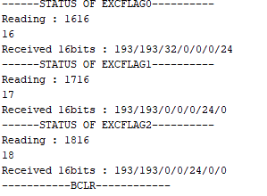
2. Because I got the flag on Excetpion B, I wanted to check the status of EXCFLAGn. 

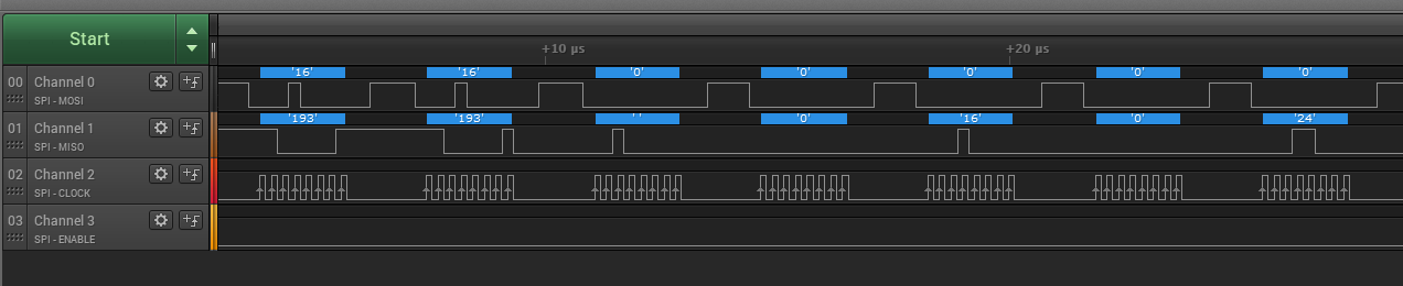
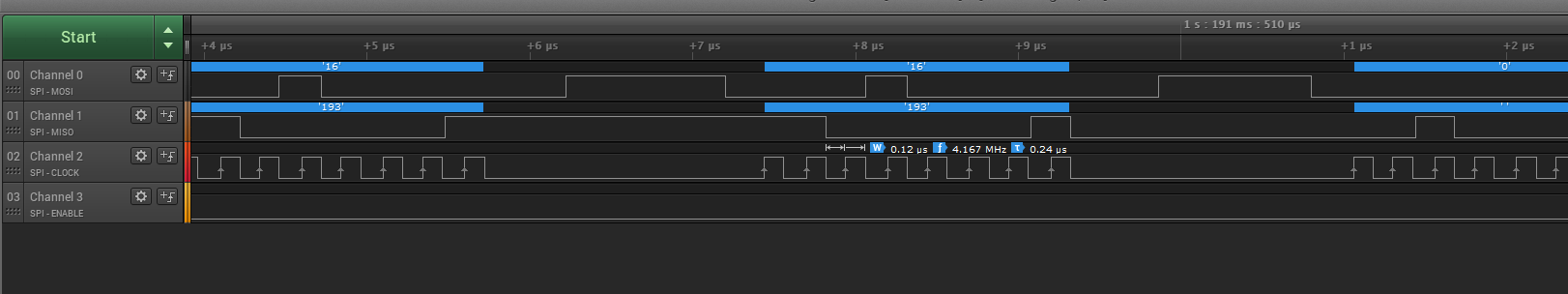
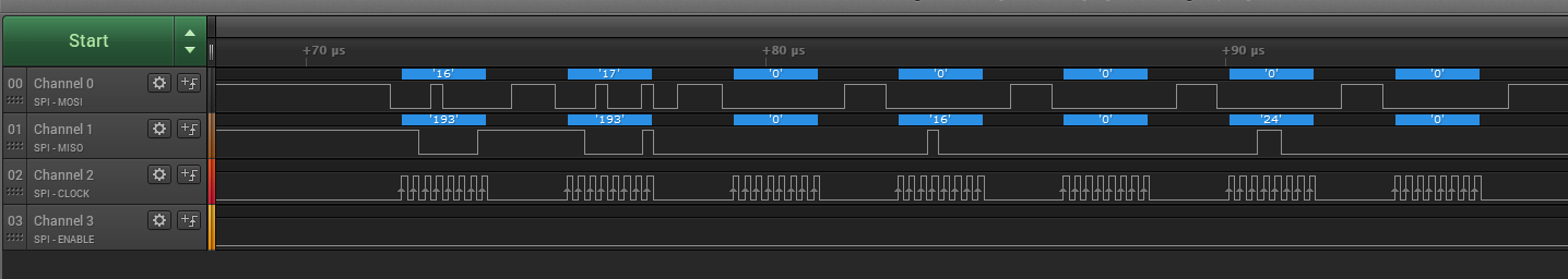
    rcv = mySPI.transfer(MEMRD_ADDRESS);      //0b'00010000    MEMRD instruction + first 4 bits of EXCFLAGn
    rcv_1 = mySPI.transfer(LO_UINT16(addr));     //last 8 bits of EXCFLAGn
    rcv_2 = mySPI.transfer(0x00);              //dummy data to get the data bits for the status of EXCFLAGn
    rcv_3 = mySPI.transfer(0x00);              //dummy data to get the data bits for the status of EXCFLAGn 
    rcv_4 = mySPI.transfer(0x00);              //dummy data to get the data bits for the status of EXCFLAGn  
    rcv_5= mySPI.transfer(0x00);              //dummy data to get the data bits for the status of EXCFLAGn  

According to the datasheet, I can get the 2 bytes of  status , and then followed up 1 byte of data, which is the status of EXCFLAGn. However, this is what I got "193/193/193/12/8/0" (decimal). I got 3 times of status byte and then some weird numbers following them when I send extra strobes. For examlple, when I try to read register EXCFLAG0, it is supposed to have 2 status byte and then one byte of data. Why I keep getting different numbers when I send dummy number through SPI.

  • Hi Charles,

    Can you provide a logic analyzer or oscilloscope screenshot of your SPI communicaiton and confirm that it follows the timing requirements from section 10.5 of the CC2520 datasheet?  SCLK is default low and captures on a rising edge.  https://www.ti.com/lit/ds/symlink/cc2520.pdf 

    You can also reference the CC2520 Software Examples: https://www.ti.com/lit/zip/swrc090 

    I highly recommend that you consider a SimpleLink CC1352R1, CC1352P, or CC2652R1 device to evaluate Z-Stack which is updated quarterly alongside SIMPLELINK-CC13X2-26X2-SDK.

    Regards,
    Ryan

  • Hi Ryan,

    Thanks for your reply. All the screenshots below are based on programming on the receiver side.

    When I set up as a receiver, the status looks right. 

    And these are the screenshots when I tried to get EXCFLAG0' status. I made a mistake on address bit shift before, that is why the response from the cc2520 chip looks wrong. The one from MISO missing shows as '32' in Serial Monitor.

    Is it normal sometimes the clock has a bit different frequency? I can see sometimes one period is 0.24 us while sometimes is 0.26 us. The frequency I set up is 4MHZ.

    Screenshot for EXCFLAG1.

    The 

    If I understand it correctly. EXCFLAG0 has TX_ACK_DONE at high, and EXCFLAG2 has SPI_ERROR high. Why the SPI_ERROR is high, it seems that I can get the information from CC2520 chip via SPI communication, then why there is SPI_ERROR?

    Updates: I wrote 0 to all three EXCFLAG at initialization, then the SPI_ERROR goes low while TX_ACK_DONE is still high. Is it supposed to be high when I do not have any setting on TX?

    Sorry, too many questions. Any advice will helpful, thanks!

  • I recommend keeping CSn high between operations, then pulling low before executing the REGRD/MEMRD command.  SCLK variance is fine so long as it does not go above 8 MHz.  For MEMRD, output data is a byte long and only valid after the first two full input bytes (Table 11/12).  EXCFLAG0 exists at address 0x10 (Table 20) so you should write {0x16, 0x16} (which you appear to have done) then receive the EXCFLAG0 data in the third byte (0x20 indicates RX_UNDERFLOW since MSB first, under the same logic EXCFLAG2 is RF_NO_LOCK).  I'm not sure why the other read bytes are used but as you can see it will simply continue to read out memory sequentially (EXCFLAG0, EXCFLAG1, EXCFLAG2, etc).  0xC1 is just status bytes (Table 13) for XOSC stable, valid RSSI, and RX active.  Please follow the flow diagrams and tips/tricks from the Datasheet and look though other E2E posts regarding the CC2520: https://e2e.ti.com/search?q=cc2520&category=forum 

    Regards,
    Ryan

  • Hi Ryan,

    Thanks for your patience and clear explanation.

    Last three questions (I wish, haha)  after reading  the datasheet.

    1. I went back to set up STXON to enable TX mode. I got '9' in EXCFLAG0, which means TX_UNDERFLOW AND RF_IDLE are high. According the FSM diagram, the state will go back to the "idle" when the TX_underflow is high. And after 2 us, it goes to TX final and then TX shutdown, finally go to "idle". So, if I understand it correctly, whenever it is TX_underflow, it will stops TX mode and goes to "idle" mode, and I need to enable the TX mode again when I need it, right?

    2. Since there is TX_underflow flag, I tried to add some garbage data to the TXBUF to see if any changes happened.

    According to Figure 16, I wrote number 5 (length) and 3 garbage bytes to the TXBUF (AUTOCRC is 1). After written, I checked the TXFIFOCNT, it gave me 4 bytes data in TXFIFO, which looks right. And then after enabling TX, the byte number in TXFIFOCNT remains at 4. I also set FRMCTRL1.IGNORE_TX_UNDERFLOW to high, which tried to avoid error of underflow and forbids it going to "idle" state automatically. (BUT IT STILL GOES TO IDLE STATE)

    I check EXCFLAG0 right after enabling TX, I got RF_IDLE and TX_FRM_DONE high. It seems very hard to catch the TX_ACTIVE status, so I want to know if it is possible to keep the status in TX wait mode, similarr to the RX (I cannot find a way from FSM diagram at datasheet). 

    3. Except the source address, destination address, frequency, and channel, iD, should I set up anything else to pair up two devices? if I don't want to make frame filtering, can I just set up frequency and channel on both TX and RX to pair them up and build the connection?

    Thanks,

    Charles

  • Hi charles,

    You are referring to Figure 17, the TX Flow Diagram, correct?  Are you performing a SFLUSHTX command and making sure that one TX completes before filling the buffer again?  But yes, you will need to send STXON again.  Please review all descriptions of SFD and TX_UNDERFLOW in the Datasheet.

    Regards,
    Ryan