This thread has been locked.

If you have a related question, please click the "Ask a related question" button in the top right corner. The newly created question will be automatically linked to this question.

CC1352P: Delay of 0.5 mSec added to post command of message transmission

Part Number: CC1352P

Hi,

I'm working on 802.15.4 with CC1352 and SDK 3_30_00_03

I saw that compared to your last SDKs, there is a big delay of 0.5 mSec from calling to post command (RF_postCmd) until the rising of the PA.

I used GPIO to measure it and it was rised right before the calling to RF_postCmd.

In the post command I sending a Tx structure, rfc_CMD_IEEE_TX_t  which chained to Rx structure of type rfc_CMD_IEEE_RX_t. 

It chained by pNextOp.

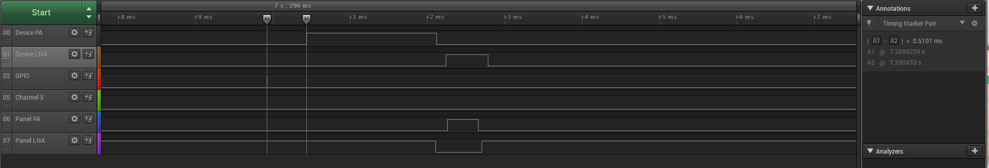
In the attached logic print you can see the device that sent a message and received ACK from the central unit. 

There is 0.51 mSec from the GPIO rise until the PA rise.

Please advise in advanced.

Thanks,

Dekel

  • Hey Dekel,

    Just to make sure I find the right person to assist, what project are you working off of?

    You mention 802.15.4, does that mean you are using the TI 15.4 Stack? Or are you using 802.15.4 commands in a proprietary solution (such as EasyLink or direct driver projects like rfPacketTx)?

  • Hi Ammar,

    We're not using TI's stack but we use your 802.15.4  APIs like  rfc_CMD_IEEE_TX_t  and rfc_CMD_IEEE_RX_t.

    Thanks,

    Dekel

  • Hi Dekel,

    Could you share how you test this? Depending on how the setup is setup you could have quicker or slower "post-to-run" time depending on if the RF Core is powered up already and if the driver needs to configure and patch the radio prior to sending out your command.

  • Hi,

    I attached my RF settings files which based on smart RF studio.

    The RX was switched off on sending the post command of the transmission.

    The GPIO was set right before calling the post command and I measured the gap between this GPIO rise and the PA rise.

    The Tx command is chained to a Rx command by pNextOp.

    This is my code:

    cmdTxEcop2.pPayload = LocalTxBuffer;
    cmdTxEcop2.payloadLen = Length;
    cmdTxEcop2.pNextOp = (rfc_radioOp_t*)&RF_cmdRxEcop2;
    cmdTxEcop2.startTrigger.triggerType = TRIG_NOW;
    cmdTxEcop2.startTime = 0;
    cmdTxEcop2.condition.rule = COND_ALWAYS;

    RF_cmdRxEcop2.endTrigger.triggerType = TRIG_NEVER;
    RF_cmdRxEcop2.endTime = 0;

    currentAsyncCmdHandle = RF_postCmd(rfHandle, (RF_Op*)&cmdTxEcop2, RF_PriorityNormal, TxDoneCallback, GetEventMask());

    LocalTxBuffer and Length are related to the sent packet.

    The type of cmdTxEcop2 is rfc_CMD_IEEE_TX_s and the type of RF_cmdRxEcop2 is rfc_CMD_IEEE_RX_s.

    GetEventMask returns 0xFFFFFFFFFFFFFFFF.

    Thanks,

    Dekel

    //*********************************************************************************
    // Generated by SmartRF Studio version 2.7.0 (build #108)
    // Tested for SimpleLink SDK version: CC13x0 SDK 1.30.xx.xx
    // Device: CC1350 Rev. 2.1 (Rev. B)
    //
    //*********************************************************************************
    
    
    //*********************************************************************************
    // Parameter summary
    // Address: off
    // Address0: 0xAA
    // Address1: 0xBB
    // Frequency: 870.00000 MHz
    // Data Format: Serial mode disable
    // Deviation: 16.000 kHz
    // Packet Length Config: Variable
    // Max Packet Length: 255
    // Packet Length: 12
    // RX Filter BW: 98 kHz
    // Symbol Rate: 38.40027 kBaud
    // Sync Word Length: 16 Bits
    // TX Power: 6 dBm (requires define CCFG_FORCE_VDDR_HH = 0 in ccfg.c, see CC13xx/CC26xx Technical Reference Manual)
    // Whitening: No whitening
    
    
    #include <smartrf_settings_ecop2.h>
    #include <ti/devices/DeviceFamily.h>
    #include DeviceFamily_constructPath(driverlib/rf_mailbox.h)
    #include DeviceFamily_constructPath(driverlib/rf_common_cmd.h)
    #include DeviceFamily_constructPath(driverlib/rf_ieee_cmd.h)
    #include <ti/drivers/rf/RF.h>


    #ifdef DeviceFamily_CC13X0
    // Overrides for CMD_PROP_RADIO_DIV_SETUP
    static uint32_t pOverrides[] =
    {
        // override_use_patch_prop_genfsk.xml
        // PHY: Use MCE ROM bank 4, RFE RAM patch
        MCE_RFE_OVERRIDE(0,4,0,1,0,0),
        // override_synth_prop_863_930_div5.xml
        // Synth: Set recommended RTRIM to 7
        HW_REG_OVERRIDE(0x4038,0x0037),
        // Synth: Set Fref to 4 MHz
        (uint32_t)0x000684A3,
        // Synth: Configure fine calibration setting
        HW_REG_OVERRIDE(0x4020,0x7F00),
        // Synth: Configure fine calibration setting
        HW_REG_OVERRIDE(0x4064,0x0040),
        // Synth: Configure fine calibration setting
        (uint32_t)0xB1070503,
        // Synth: Configure fine calibration setting
        (uint32_t)0x05330523,
        // Synth: Set loop bandwidth after lock to 20 kHz
        (uint32_t)0x0A480583,
        // Synth: Set loop bandwidth after lock to 20 kHz
        (uint32_t)0x7AB80603,
        // Synth: Configure VCO LDO (in ADI1, set VCOLDOCFG=0x9F to use voltage input reference)
        ADI_REG_OVERRIDE(1,4,0x9F),
        // Synth: Configure synth LDO (in ADI1, set SLDOCTL0.COMP_CAP=1)
        ADI_HALFREG_OVERRIDE(1,7,0x4,0x4),
        // Synth: Use 24 MHz XOSC as synth clock, enable extra PLL filtering
        (uint32_t)0x02010403,
        // Synth: Configure extra PLL filtering
        (uint32_t)0x00108463,
        // Synth: Increase synth programming timeout (0x04B0 RAT ticks = 300 us)
        (uint32_t)0x04B00243,
        // override_phy_rx_aaf_bw_0xd.xml
        // Rx: Set anti-aliasing filter bandwidth to 0xD (in ADI0, set IFAMPCTL3[7:4]=0xD)
        ADI_HALFREG_OVERRIDE(0,61,0xF,0xD),
        // override_phy_gfsk_rx.xml
        // Rx: Set LNA bias current trim offset to 3
        (uint32_t)0x00038883,
        // Rx: Freeze RSSI on sync found event
        HW_REG_OVERRIDE(0x6084,0x35F1),
        // override_phy_gfsk_pa_ramp_agc_reflevel_0x1a.xml
        // Tx: Configure PA ramping setting (0x41). Rx: Set AGC reference level to 0x1A.
        HW_REG_OVERRIDE(0x6088,0x411A),
        // Tx: Configure PA ramping setting
        HW_REG_OVERRIDE(0x608C,0x8213),
        // override_phy_rx_rssi_offset_5db.xml
        // Rx: Set RSSI offset to adjust reported RSSI by +5 dB
        (uint32_t)0x00FB88A3,
        // TX power override
        // Tx: Set PA trim to max (in ADI0, set PACTL0=0xF8)
        ADI_REG_OVERRIDE(0,12,0xF8),
        (uint32_t)0xFFFFFFFF,
    };
    
    #endif
    
    
    #ifdef DeviceFamily_CC13X2
    // Overrides for CMD_RADIO_SETUP_PA
    uint32_t pOverridesEcop2[] =
    {
        // override_ieee_802_15_4.xml
        // Rx: Set LNA bias current offset to +15 to saturate trim to max (default: 0)
        (uint32_t)0x000F8883,
        (uint32_t)0xFFFFFFFF
    };
    
    // Overrides for CMD_RADIO_SETUP_PA
    uint32_t pOverridesTxStdEcop2[] =
    {
        // The TX Power element should always be the first in the list
        TX_STD_POWER_OVERRIDE(0x941E),
        // The ANADIV radio parameter based on the LO divider (0) and front-end (0) settings
        (uint32_t)0x05320703,
        (uint32_t)0xFFFFFFFF,
    };
    
    
    // Overrides for CMD_RADIO_SETUP_PA
    uint32_t pOverridesTx20Ecop2[] =
    {
        // The TX Power element should always be the first in the list
        TX20_POWER_OVERRIDE(0x003F5BB8),
        // The ANADIV radio parameter based on the LO divider (0) and front-end (0) settings
        (uint32_t)0x01C20703,
        (uint32_t)0xFFFFFFFF,
    };
    
    #endif
    
    
    // CMD_RADIO_SETUP_PA
    // Radio Setup Command for Pre-Defined Schemes
    rfc_CMD_RADIO_SETUP_PA_t RF_cmdPropRadioSetupEcop2 =
    {
        .commandNo = 0x0802,
        .status = 0x0000,
        .pNextOp = 0, // INSERT APPLICABLE POINTER: (uint8_t*)&xxx
        .startTime = 0x00000000,
        .startTrigger.triggerType = 0x0,
        .startTrigger.bEnaCmd = 0x0,
        .startTrigger.triggerNo = 0x0,
        .startTrigger.pastTrig = 0x0,
        .condition.rule = 0x1,
        .condition.nSkip = 0x0,
        .mode = 0x01,
        .loDivider = 0x00,
        .config.frontEndMode = 0x0,
        .config.biasMode = 0x0,
        .config.analogCfgMode = 0x0,
        .config.bNoFsPowerUp = 0x0,
        .txPower = 0x941E,
        .pRegOverride = pOverridesEcop2,
        .pRegOverrideTxStd = pOverridesTxStdEcop2,
        .pRegOverrideTx20 = pOverridesTx20Ecop2
    };
    
    rfc_CMD_IEEE_TX_t cmdTxEcop2 =
    {
        .commandNo                  = 0x2C01,
        .status                     = 0x0000,
        .pNextOp                    = 0, // INSERT APPLICABLE POINTER: (uint8_t*)&xxx
        .startTime                  = 0x00000000,
        .startTrigger.triggerType   = 0x0,
        .startTrigger.bEnaCmd       = 0x0,
        .startTrigger.triggerNo     = 0x0,
        .startTrigger.pastTrig      = 0x0,
        .condition.rule             = 0x1,
        .condition.nSkip            = 0x0,
        .txOpt.bIncludePhyHdr       = 0,
        .txOpt.bIncludeCrc          = 0,
        .txOpt.payloadLenMsb        = 0,
        .payloadLen                 = 0x1E,
        .pPayload                   = 0x00000000,
        .timeStamp                  = 0x00000000,
    };
    
    //Rx command
    // CMD_IEEE_RX
    rfc_CMD_IEEE_RX_t RF_cmdRxEcop2 =
    {
        .commandNo                          = 0x2801,
        .status                             = 0x0000,
        .pNextOp                            = 0, // INSERT APPLICABLE POINTER: (uint8_t*)&xxx
        .startTime                          = 0x00000000,
        .startTrigger.triggerType           = 0x0,
        .startTrigger.bEnaCmd               = 0x0,
        .startTrigger.triggerNo             = 0x0,
        .startTrigger.pastTrig              = 0x0,
        .condition.rule                     = 0x1,
        .condition.nSkip                    = 0x0,
        .channel                            = 0x0,
        .rxConfig.bAutoFlushCrc             = 1,
        .rxConfig.bAutoFlushIgn             = 1,
        .rxConfig.bIncludePhyHdr            = 1,
        .rxConfig.bIncludeCrc               = 0,
        .rxConfig.bAppendRssi               = 1,
        .rxConfig.bAppendCorrCrc            = 1,
        .rxConfig.bAppendSrcInd             = 0,
        .rxConfig.bAppendTimestamp          = 1,
        .pRxQ                               = 0x00000000,
        .pOutput                            = 0x00000000,
        .frameFiltOpt.frameFiltEn           = 1,
        .frameFiltOpt.frameFiltStop         = 1,
        .frameFiltOpt.autoAckEn             = 1,
        .frameFiltOpt.slottedAckEn          = 0,
        .frameFiltOpt.autoPendEn            = 1,
        .frameFiltOpt.defaultPend           = 0,
        .frameFiltOpt.bPendDataReqOnly      = 0,
        .frameFiltOpt.bPanCoord             = 0,
        .frameFiltOpt.maxFrameVersion       = 3,
        .frameFiltOpt.fcfReservedMask       = 1,
        .frameFiltOpt.modifyFtFilter        = 0,
        .frameFiltOpt.bStrictLenFilter      = 0,
        .frameTypes.bAcceptFt0Beacon        = 1,
        .frameTypes.bAcceptFt1Data          = 1,
        .frameTypes.bAcceptFt2Ack           = 1,
        .frameTypes.bAcceptFt3MacCmd        = 1,
        .frameTypes.bAcceptFt4Reserved      = 1,
        .frameTypes.bAcceptFt5Reserved      = 1,
        .frameTypes.bAcceptFt6Reserved      = 1,
        .frameTypes.bAcceptFt7Reserved      = 1,
        .ccaOpt.ccaEnEnergy                 = 0,
        .ccaOpt.ccaEnCorr                   = 0,
        .ccaOpt.ccaEnSync                   = 0,
        .ccaOpt.ccaCorrOp                   = 1,
        .ccaOpt.ccaSyncOp                   = 1,
        .ccaOpt.ccaCorrThr                  = 0,
        .ccaRssiThr                         = 0x64,
        .__dummy0                           = 0x00,
        .numExtEntries                      = 0x00,
        .numShortEntries                    = 0x00,
        .pExtEntryList                      = 0x00000000,
        .pShortEntryList                    = 0x00000000,
        .localExtAddr                       = 0x0000000012345678,
        .localShortAddr                     = 0xabba,
        .localPanID                         = 0x0000,
        .__dummy1                           = 0,
        .endTrigger.triggerType             = 1,
        .endTrigger.bEnaCmd                 = 0,
        .endTrigger.triggerNo               = 0,
        .endTrigger.pastTrig                = 0,
        .endTime                            = 0x00000000,
    };
    
    rfc_CMD_IEEE_RX_ACK_t RF_cmdRxAckEcop2 =
    {
        .commandNo                          = CMD_IEEE_RX_ACK,
        .status                             = IDLE,
        .pNextOp                            = 0, // INSERT APPLICABLE POINTER: (uint8_t*)&xxx
        .startTime                          = 0x00000000, //now
        .startTrigger.triggerType           = TRIG_NOW,
        .startTrigger.bEnaCmd               = 0x0,
        .startTrigger.triggerNo             = 0x0,
        .startTrigger.pastTrig              = 0x0,
        .condition.rule                     = COND_NEVER,
        .condition.nSkip                    = 0x0,
        .seqNo                              = 0x0, //should be set by the user
        .endTrigger.triggerType             = TRIG_REL_START,
        .endTrigger.bEnaCmd                 = 0,
        .endTrigger.triggerNo               = 0,
        .endTrigger.pastTrig                = 1,
        .endTime                            = 0x00001f40, //8000 decimal, 2ms according to 4Mhz radio frequency
    };
    
    rfc_CMD_IEEE_MOD_FILT_t RF_cmdModifyFilterEcop2 =
    {
        .commandNo                         = CMD_IEEE_MOD_FILT,
        .newFrameFiltOpt                   = 0,
        .newFrameTypes                     = 0,
    };
    
    rfc_CMD_IEEE_MOD_SRC_MATCH_t RF_cmdSrcMatchEcop2 =
    {
        .commandNo                          = CMD_IEEE_MOD_SRC_MATCH,
        .options.bEnable                    = 0,
        .options.srcPend                    = 0,
        .options.entryType                  = 0,
        .entryNo                            = 0,
    };
    
    smartrf_settings_ecop2.h

  • Hi Dekel,

    I would have expected a "RF_Mode" struct (passing into the RF_open() API), is this defined somewhere else in your application?

    There is a few things to consider in this case. First of is the CC1352P really assumes the radio to be patched in order for the PA switching to work as expected. The presence of a patch will add to the radio "wake-up" time, I would say 150-200 us would be a reasonable headroom number for this patch to be performed. The patch time could be quicker in case the radio was already patched once before (as there is some level of retention in the radio RAM) but for now we assume a "cold boot" of the radio. 

    Coming from a cold boot, there is a few things that would need to happen before the radio is ready to TX:

    1) The driver would need to turn on and swtich to XOSC HF as it is typically not in use when the radio is of (to save power). This is to some degree able to run in parallel but it is still some processing time needed.

    2) The radio need to be booted up and configured. This would include the patching etc. 

    Assume 1 and 2 could be done in parallel and the processing time is "small", we could choose to count with patch time only: ~150 us.

    3) The driver would need to run the "Setup" and "FS" command to get the radio properly running before TX. This would add additional time to the "responds" where the FS is likely the largest portion of this as the synthesizer would need lock. Just a ball park number here, 100-150 us might be a good number.

    A thing you could do here is to also route out the "Calibration done" radio signal to a IO and observe this alongside the other IOs. This will show you the delay from "post" to "calibration done" to "PA enable". It should help give a better picture of where most of the delay is located.

    Assume we now have at least 300 us worth of processing done and now are ready to start the TX, there is internal processing delays related to setting up and priming TX buffers etc etc. Accounting for a 90-100 us delay here.

    We are now at ~400 us (based on the assumptions above). This is not considering any of the processing delays in the device (interrupts that need to bounce back and forth between the CM4 and the Radio Core, the RD driver state machine etc etc) which could quickly add up to a few us worth of "delay" as well.

    To boil everything down, ~500us is not an unreasonable number assuming the radio is booted up from complete shutdown. I would assume the number to be smaller if you ran the exact same command again without turning of the radio or going into standby (as the radio should be up and running already).

    Could you test this in addition to routing out the calibration signal (CPE_GPO2) and observing this?

    https://dev.ti.com/tirex/explore/node?a=pTTHBmu__3.20.00.68&node=AOFmdaK8impnxmEqGU3jkg__pTTHBmu__LATEST