This thread has been locked.

If you have a related question, please click the "Ask a related question" button in the top right corner. The newly created question will be automatically linked to this question.

CC2530: Not recognized by CC Debugger

Part Number: CC2530
Other Parts Discussed in Thread: CC-DEBUGGER, CC2531EMK, CC2531

Hi,

the last days I tried to flash my CC2530 but couldn't get the TI CC Debugger to recognize the chip.

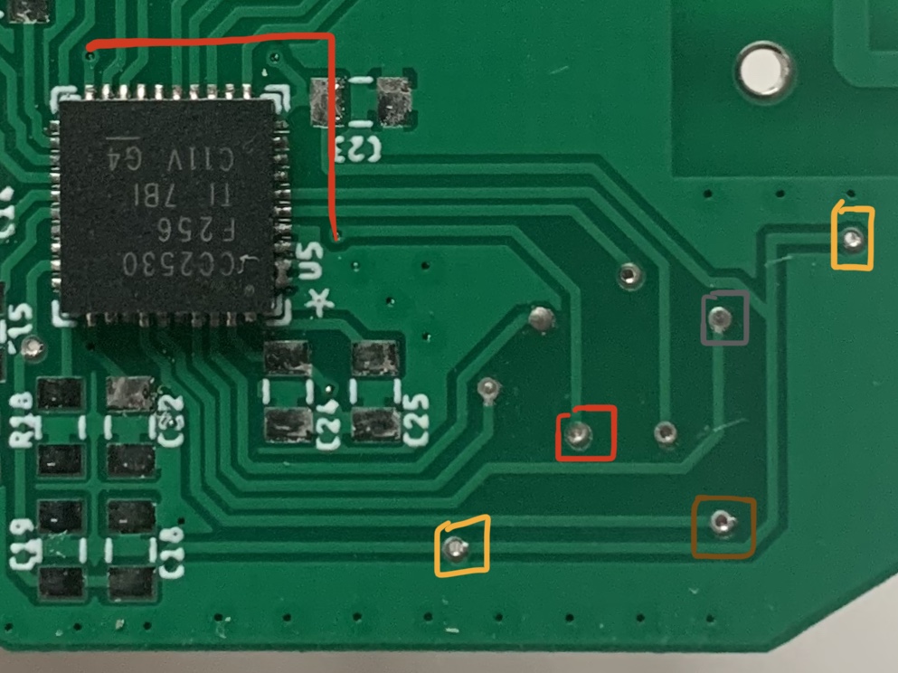
The connections are the following:

Debugger -> Chip

GND -> GNDs

Target Voltage Sense -> VCCs

DD -> P2.1

DC -> P2.2

RESET -> RESET

3.3V -> VCCs

I also measured the ribbon cable through and there should be no problem. The USB cable should be fine as well, as the CC Debugger is getting recognized just fine by the PC.

Currently I have no components other than the debug-connector attached to the chip. Are other components essential to connect so I can flash the chip succesfully (e.g. external RF-clock)?

Best regards,

Dieter

  • Hi Dieter,

    Your description of connections between the CC-DEBUGGER and CC2530 is correct so far, please follow Figure 6 from SWRU197 (including the RESETn RC filter) and reference the CC2531EMK design to ensure that all connections are valid.

    Regards,
    Ryan

  • Hi Ryan,

    thanks for the quick reply.

    Just tested your suggestion of implementing the RC filter on the RESETn line. Unfortunately I still can't get my chip connected to the Debugger. Do you think a 10nF instead of a 1nF cap makes a difference here?
    I also looked at the reference design of the CC2531EMK stick and the debug interface looks the same to mine (after I added the RC filter).

    Do you have another idea what it could be?

    Best regards,
    Morris

  • Hello Morris,

    Poor physical connections to the CC2530 debug pins will interfere with the JTAG connection, you should further investigate with an oscilloscope or logic analyzer.  Reset line capacitance makes a difference.

    Regards,
    Ryan

  • From the text and the picture it could sound like you have just mounted the chip on the PCB? 

  • Thank you for the replies.


    That is true TER, in this regard I have not expressed myself properly. The pictures my colleague sent were also a bit misleading, but on the blank board you can see the tracks better. 

    I tried to flash a fully assembled board with no luck. Now I want to flash a PCB with just the necessary parts soldered on, so I can at least flash the chip (hopefully). Which parts are absolutely necessary for flashing the CC2530?


    Best regards,
    Dieter

  • You need to connect:

    - RBIAS

    - 32 MHz xtal

    - DCOUPL

    - Power on all VDD pins. 

    From the pictures it looks like you don't have a connector for debugging/ flashing. 

    Which voltage level do you measure on the RBIAS (should be ~1.24 V) and DCOUPL (Should be ~1.78 V)?

  • Hello TER,

    perfect, thank you.

    The connector is right on the backside of the PCB and not visible on the picture. It's just a standard 10 pin, 2 row, 2.54mm pitch connector.
    On my fully assambled board I measured the following: RBIAS 1.26V and DCOUPL 1.84V @ VCC ~3.24V.

    I will solder a new module with just the components you mentioned today afternoon.
    Also I will also measure the RESETn, DC and DD connections with my scope later . I also implemented an 1nF cap and the resistor just like on the CC2531 stick. No luck so far.

    Cheers,
    Dieter

  • I just resolved th issue (for now) by soldering the neccessary components mentioned by TER onto a new PCB.

    Now I will solder each component group on seperatly and test the debug connection inbetween. Hopefully I will figure out the problemtic group.

    Thanks guys!

    Dieter