This thread has been locked.

If you have a related question, please click the "Ask a related question" button in the top right corner. The newly created question will be automatically linked to this question.

CCS/CC2650: Custom PCB fail to download any program

Part Number: CC2650
Other Parts Discussed in Thread: CC2640

Tool/software: Code Composer Studio

Hi everyone! We have designed a custom PCB mounting the CC2650F128RSM (4x4 mm ) and we are now experiencing the following situation:

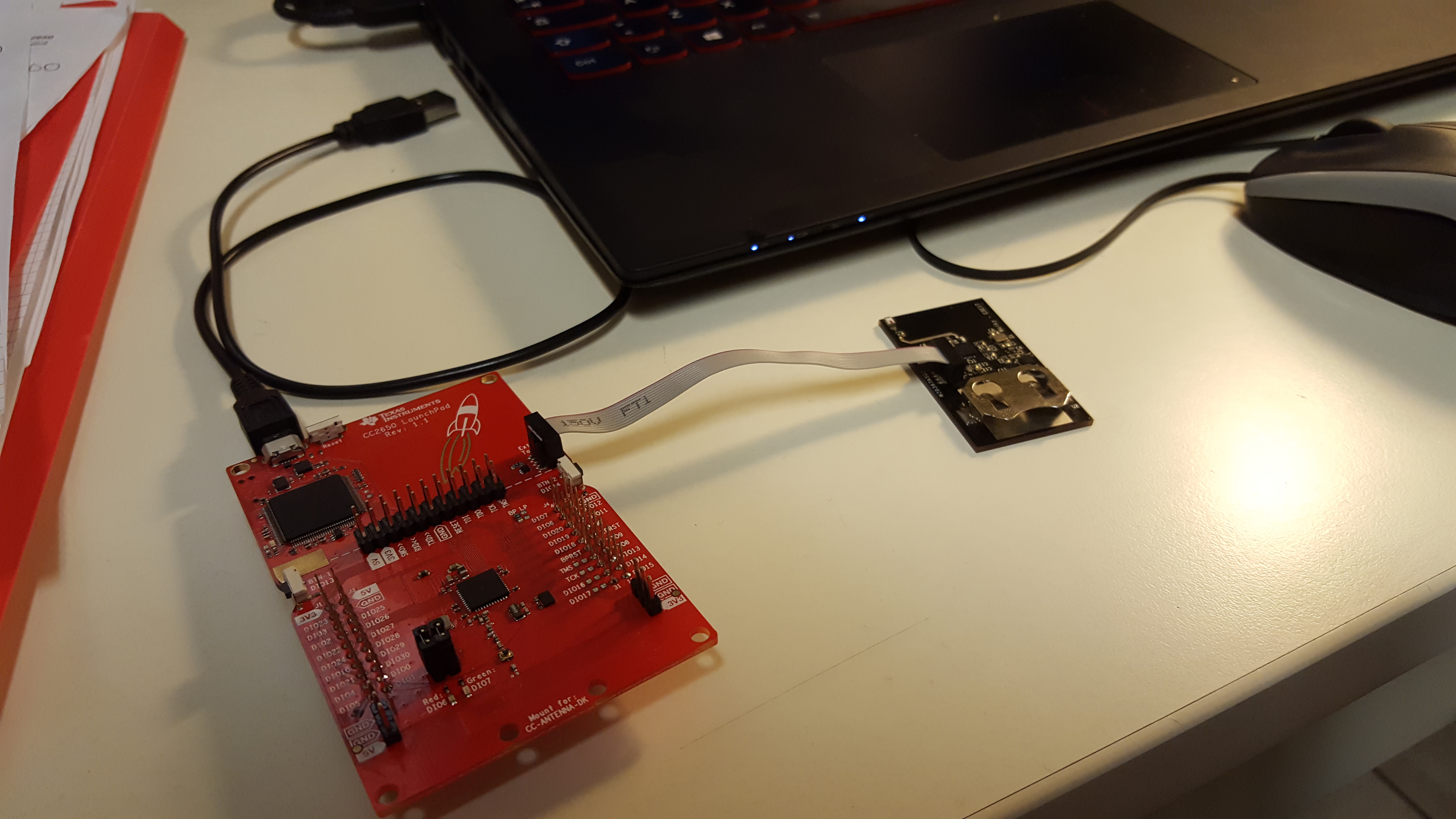
We are usign the LaunchPad cc2650 rev 1.1 to act as a programmer, with the xds110 debugger platform (connecting the debugger to the external target)

1. Flash Programmer 2 Studio is able to correctly detect the microcontroller, read the flash memory, erase it, acquire information about MAC addresses and eventually program it downloading some binary files (samples and tests of Flash Programmer 2 Studio) into our target microcontroller. Without any apparent problem (with a successful outcome).

2. SmartRF Studio, on the contrary, is able to detect it but as soon as it is launched it quickly overheats the microcontroller case, we are not able to perform any further operation (like changing the target device or others). We have to disconnect it and erase the flash to remove any program on it and cool it down. 

3. On Code Composer Studio, we have tried to use some template projects (we actually tried also the hello world, but we experienced the well-known issues about linking other libraries and successfully building the project) so we ended up by expoiting the BLE stack 2.02.01.18. The building is completed as well as the downloading of the stack (without any "hot" problem), but as soon as we try to download the app, the problem of overheating reappears. 

4. Sensor Controller Studio presented the same overheating when trying to upload the Uart Emulator project example. As SmartRF Studio, as soon as we connect to the microcontroller, the overheating appears. We need to disconnect immediately and erase the flash with Flash Programmer. 

We would like to exclude any issue regarding a wrong choice of package: we have noticed all the programs come with the default 7x7 mm package versions. Is the compiler and the downloader able to adjust and recognise the different package (on the BLE Stack's development guide it is suggested, in order to build everything correctly, not to change the version of the target leaving it as default. 

Since it is one of our first PCB design, we also tried to exclude any problem related to the physical assembly of components. We checked for some shorts, at least the visible ones.

Some questions:

>     Can it depend on the thermal central pad? We grounded it but we are not sure it is completely solded to the board. 

>     Can it depend on some SW configuration not aligned with our design?

>     How could we avoid any problems of reflections, keeping the RF module completely shut down while we use our CC2650 to run other applications?

>     In the proposed attachment,  our schematics: we followed the design adopted for the Sensor Tag, we are using the RF module with internal BIAS, using the DC_DC switch and operating in differential mode. 

WALKY_schematics.pdf

Thanks to everyone for any suggestions, ideas and answers for relieving our CC2650 by any other sufference!     :(

Have a nice day! :) 

  • Hello Marco,

    If you are observing heat this means you likely have a short on your board or you have somehow damaged the CC2640 MCU. You do need to connect the ground plane as described in the "HW design checklist for CC2640" article on the TI BLE Wiki.

    You are using a differential / internal bias RF configuration, which equates to the CC2650EM_7ID settings, although your board file should not use more IOs than DIO_9.

    I suggest doing a thorough electrical short check and completing the check items on the "CC2640 HW Troubleshooting & Bring Up" wiki article.

    Best wishes
  • Part Number: CC2650

    Hi everyone, I posted a few hours ago about an overheating problem we are experiencing with our cc2650f128RSM custom PCB.

    Here you can read the previous thread   -- >        e2e.ti.com/.../598739

    For a complete check I will upload the schematic (PDF) with all the allegro files (to review the design). 

    Here some design specifications we followed from TI guidelines:

    - DCDC internal regulator approach

    - both 24MHz and 32.748 KHz XOSC mounted on the board, the first one without any cap., the second with external capacitors

    - Debugging with Launchpad v1.1

    We had noticed a strange overheating when using Smart RF Studio (but not with Flash Programmer 2) and when running any code on it using both Cloud CCS and CCS.

    TI assistance member suggested us to check for electric shorts and to make sure the EGP was correctly soldered: yesterday we soldered a NEW component (always a CC2650F128RSM - 4x4 mm) on the PCB, carefully checking the possibility of shorts between pins, but the overheating problem is still present. 

    We are able to correctly download any program, make it run (it reaches different breakpoints (like in the power policy Standby configuration)) we have been even able to see a GPIO correctly configured as HIGH (with all the others disabled in order to avoid any short on GPIOs). All PWM, RF, UART have been removed from the project in order to selectively get the cause of the excess of heat.

    We changed some parameters on ccfg.c files (e.g. tried with RC LF OSC or enabling the CAP ARRAY for the HF XOSC). The complete project is attached down here. I can't keep the debugger opened for a long time (sniffing registers content, clock status, etc...) because I would like to avoid any thermal damage to our IC.

    We suspect there might be some design issues for what concerns the DCDC_SW, VDDR pins, etc...or, possibly, some damage in the quartz oscillator (in this case we have tried to exploit the internal HF oscillator, but didn't find any resource online to understand how).

    Have you got any suggestions on what the problem might be or what other procedure we could adopt to exclude faults and defects?  Thanks in advance for your much appreciated help! :)

    Design Schematic PDF

    5078.WALKY_schematics.pdf

    Layout, Allegro BRD

    WALKY_v02.zip

    Customized applications files

    hello_CC2650DK_7ID_TI.zip

    Marco

  • Hello Marco,

    I've merged your posts since they are covering the same topic - please use this thread for troubleshooting your board. Can you attach a photo of you debug setup? Do you see the thermal issue if you do not run with the JTAG attached but use the standby example?

    Best wishes
  • Thank you very much! Sorry if I didn't use the same thread. Here the picture of the debugging setup. I tried to download the program on the board, unplug the JTAG connector and power the board with the CR2032 and it correctly executes the code (GPIO1 is correctly initialised to HIGH). The overheating is always present, unfortunately. Obviously being the battery a cr2032 of 3 V (I measured 2.45 V) the phenomenon is less evident, but I can experience a mild heating   (which means our battery is discharging very fast).  I am attaching the picture you asked me.

  • Thank you. Where is your 10uH inductor on the DCDC_SW? I don't see it on your schematic.

    Also, your 24M crystal is likely out of spec, although I don't see that as the cause for the over current.

    Best wishes
  • Hi Marco,

    JXS has pointed out your problem. Connecting DCDC-SW directly to VDDR will not work. I am actually surprised you are able to run code on the board.

    Try cutting the DCDC-SW trace (leave the 10 uF capacitor connected to VDDR) .

    Cheers,
    Fredrik
  • We did not include it in our design because it is said to be optional... Actually, DCDC operation (that is when is needed) is our case right? :(    

    Do you think this missing inductor is the problem?   We will check also for the quartz... we will try to find a model compatible with the specs... Thanks for your help! 

  • Thanks Fredrik! I am sorry but I noticed your message after I replied. So you mean that by cutting the trace the problem will be solved? Will I be able to use GPIOs and RF modules? Thank you for your answer!
  • The inductor being optional does not mean it is ok to to connect DCDC-SW to VDDR. Refer to figure 7-2 in the CC2650 datasheet. Unless there are other problems cutting the trace should resolve the issue.
  • Thank you! Cutting the trace definetely solved our issue! RF is not affected either! Thanks a million for your suggestion :)

  • That´s good to hear!