This thread has been locked.

If you have a related question, please click the "Ask a related question" button in the top right corner. The newly created question will be automatically linked to this question.

UART TX Very Weak when using SensorTag 2 Debug DevPack

Other Parts Discussed in Thread: CC2650, CC2650STK, BLE-STACK

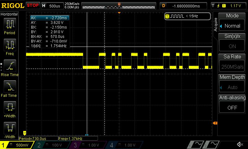
I am using the SensorTag 2 Debug DevPack Rev 1.2, and have configured it to use DP4 (UART RX) and DP5 (UART TX). But for some reason the amplitude for TX is very weak, 710mV instead of 3.3V (see image)

I am using the uartecho_CC2650F128 example that comes as with TI-RTOS, And made a few changes to configure it to use the debug devpack pins (see code changes below)

I have also seen the same issue discussed here (e2e.ti.com/.../423180) but it makes no difference if I have the battery in or not. I need to have this working when debugging.

I made the following changes to board.c located in C:\ti\tirtos_simplelink_2_13_01_09\packages\ti\boards\SensorTag\CC26XXST_0120

// Changed Board_DP5_UARTTX from PIN_INPUT_EN to PIN_GPIO_OUTPUT_EN
PIN_Config BoardGpioInitTable[] = {
:
    Board_DP4_UARTRX | PIN_INPUT_EN | PIN_PULLDOWN,                                           /* DevPack */
    Board_DP5_UARTTX | PIN_GPIO_OUTPUT_EN | PIN_PULLDOWN,                                     /* Devpack */
:
};

// Changed the .txPin and .rxPin as shown below
const UARTCC26XX_HWAttrs uartCC26XXHWAttrs[CC2650_UARTCOUNT] = {
    {    /* CC2650_UART0 */
        .baseAddr = UART0_BASE,
        .intNum = INT_UART0,
        .powerMngrId = PERIPH_UART0,
        .txPin = Board_DP5_UARTTX, //Board_EB_UART_TX,
        .rxPin = Board_DP4_UARTRX, //Board_EB_UART_RX,
        .ctsPin = PIN_UNASSIGNED,
        .rtsPin = PIN_UNASSIGNED
    },
};

What can I do to resolve this issue, I want to be able to use UART using the Debug DevPack pins/vias?

Glenn.

  • Hi Glenn
    In my experience, if I connect my debugPack to PC it is a XDS110 Debugger. If I connect debugPack to sensorTag with battery then attach usb cable again it is a XDS110 debugger. but if I attach the debugger to sensorTag without battery THEN attach usb cable to debugger it appears as some tiva... device. In this case you cant use it for programming or debugging but the uart IOs are working.
    Hope it was helpful.

    Regards,
    Mohamad
  • Thanks Mohamad, Unfortunately does not help me, I am developing code and hence will need to have UART functioning while debugging. (Also I do not get the same result as you)

    TI, have I set everything up correctly, or do I need to do something else to be able to use the pin outs on the Debug DevPack?

    Glenn.
  • Is there anyone that can assist me with this issue?

    I'd imagine having UART working on the board that people will develop products with, is going to be very important!

    Is this broken? It would be great to get some response that would let me know the status, I am not the only person who has reported this issue.

    Glenn.
  • I have found a resolution to the problem.

    Do not use the default setup, instead reconfigure the pins by editing the board.h file (located in C:\ti\tirtos_simplelink_2_13_01_09\packages\ti\boards\SensorTag\CC26XXST_0120)

    TX is pin DP3 on the Debug DevPack (do not pay attention to the define name)
    RX is pin DP4 on the Debug DevPack 

    #define Board_DP3                   IOID_28 //IOID_27
    #define Board_DP4_UARTRX            IOID_29
    #define Board_DP5_UARTTX            IOID_27 //IOID_28

    The CC2650 seems to offer very flexible multiplexing options, details of any of this are yet to be included in the data sheet.

    I did find the below quote in this document - www.ti.com/.../cc2650.pdf

    "The I/O controller controls the digital I/O pins and contains multiplexer circuitry to allow a set of peripherals to be assigned to I/O pins in a flexible manner"

    Perhaps this needs to be made clearer, with a table that shows which pin can do what.

    Glenn.

  • I have the debug DevPack 1.2, and the example works for me with the original configuration of DP3, DP4, and DP5 mapped to IOID_27, IOID_28 and IOID_29 respectively.

    Thanks for pointing out the need to switch board.c from using the Board_EB_UART_x pins to Board_DPx_UARTx pins - that saved me a lot of confusion. What is SRF06EB and why is board.c connecting the UART to it by default?

    EDIT: Ah, it looks like SRF06EB is an alternative CC2650 evaluation kit.

  • Hi Robert,

    Glad to see others finding this post useful.

    Here are the details on SRF06EB - www.farnell.com/.../1886742.pdf

    Glenn.
  • I concur with Robert. I was able to get uartecho working using the default DP3/DP4/DP5 mappings.

    uartCC26XXHWAttrs change was needed.

    BoardGpioInitTable[] change was NOT needed. I believe these set the state of the GPIOs when the resource is not in use. When the resource (UART) is put in use (by call to Board_initUART() ), then it will set up the GPIO input/output directions appropriately.

    To clarify, my uartecho project =
    C:\ti\tirtos_simplelink_2_11_01_09\tirtos_simplelink_2_11_01_09_examples\TI\CC2650STK_BLE\uartecho


    Glenn, are you using the USB as COM ports, or adding an external RS-232 level shifter ?

    =======================
    To clarify for others, when you use the Debug DevPack, it will create 2 virtual COM port instances via the USB port on the Debug DevPack,
    On Windows (8.1), open Device Manager.
    Under Ports(COM & LPT), I see 2 ports
    XDS110 Class Application/User Uart (COM6)
    XDS110 Class Auxiliary Data Port (COM7)

    (Your actual COM port will vary of course)

    The uartecho application will communicate over USB to the virtual COM port "User Uart", which in my case is COM6
    App uartecho initializes to 9600,n,8,1 setting.

    For those ruminating through TI schematics, to clarify:
    Board_DP5_UARTTX = XDSET_TXD is an input on the CC2650
    Conversely, DP4_UARTRX = XDSET_RXD and is an output on the CC2650
  • Note that my observation that DP5 is a CC2650 input, and DP4 is a CC2650 output seems in conflict with the following:

    const UARTCC26XX_HWAttrs uartCC26XXHWAttrs[CC2650_UARTCOUNT] = {
    { /* CC2650_UART0 */
    .baseAddr = UART0_BASE,
    .intNum = INT_UART0,
    .powerMngrId = PERIPH_UART0,
    .txPin = Board_DP5_UARTTX,
    .rxPin = Board_DP4_UARTRX,
    .ctsPin = PIN_UNASSIGNED,
    .rtsPin = PIN_UNASSIGNED
    },
    };

    One would think that the .txpin purpose would be define the CC2650's UART TX output pin. Weird for sure. Anyone from TI ... would love it if you can comment on this.

    But I stand by my observations. I modified uartecho to echo back the received character twice, and have verified my observations with an oscilloscope.

  • Martin Sunstrum said:
    Glenn, are you using the USB as COM ports, or adding an external RS-232 level shifter ?

    I am not using the USB COM Port for the UART.

    I am designing a board, and as such I am directly connecting the UART pins from the CC2650 to the UART pin of a OBD/CAN Controller board.

  • OK, now your changes might start to make sense.

    In your first post, you indicate you are using the Debug DevPack (presumably only for debugging purposes )
    But the microcontroller in the Debug DevPack is driving your Board_DP5_UARTTX pin, and likely was also being driven by the UART on your OBD/CAN controller board.


    Bottom line ... when using the Debug DevPack, it's microcontroller is also using the UART TX/RX pins for a USB virtual COM port, and there is a potential electrical conflict with your custom hardware.

    You have effectively moved Board_DP4_UARTRX over to the original DP3 pin which is not used by the microcontroller in the Debug DevPack, and that removed the electrical conflict.

    I don't have any info on the Debug DevPack on how to prevent it from using the UART TX/RX pins.

    Thx, Martin
  • Martin,

    The XDS110 debugger on the devPack will always have UART enabled and correspondingly drive its TX pin afaik.

    Regards,
    Svend
  • Hi Glenn,

    I thought I would add our conversation here, for others to note.

    I experienced this on BLE-Stack 2.0

    I thought it might be possibly fixed using the latest RTOS/BLE-Stack 2.1 which was just released a few days ago, but it behaves in the exact same way.

    I surgically recreated my project from scratch.

    You can see my E2E posting link below.

    Thx, Martin

    =============================================================================================================

    • Hi Glenn,

      Just had a quick question on your uartecho application ...

      Have you combined that into an application with a BLE stack ... ?

      When I "move" the uartecho into an app with a BLE stack, it doesn't work ...

      See https://e2e.ti.com/support/wireless_connectivity/f/538/t/443701 

      • 6:33 AM
    • I have the same problem, cannot get uart to work with the BLE stack. They said there is an update to the BLE stack due in July, been waiting for that, but still has not arrived.

      Post your issue on E2E and I will respond saying I have the exact same issue.

      Let me know when you do

      • 6:56 AM
  • To explain my previous statement ..

    For those ruminating through TI schematics, to clarify:

    Board_DP5_UARTTX = XDSET_TXD is an input on the CC2650

    Conversely, DP4_UARTRX = XDSET_RXD and is an output on the CC2650

    Found out reason why I thought that ...

    https://e2e.ti.com/support/wireless_connectivity/f/538/p/433842/1568470#1568470 

  • Does anyone have an update on this problem?

    I too are experiencing the behavior mentioned here. Using the default uartCC26XXHWAttrs settings and Debugger Dev Pack I can get a functioning UART working via Debugger Dev Pack. I can put a DSO on the DP4 Test Point of the Debugger Dev Pack and observe a nice 0 to 3.3V Asynchronous Serial waveform.

    However, if I connect it to my own board and put a CRO on the pin, I get an Asynchronous Serial waveform approximately 2V to 3.3V. My board is only a breakout - there is nothing but a header connected to DP4. I connect the CC2650STK directly to my breakout board - the debugger is not in the stack.

    From my fiddling, so far it would appear to be a problem resulting in how the board is powered up.

    I have changed tx and rx pin declarations in uartCC26XXHWAttrs and obtained a functional breakout board, although with the UART output on DP4. I believe this is more of a work around than anything else.
  • I should add that changing uartCC26XXHWAttrs and assigning .txPin to almost any other pin except DP5 (IOID_29) seems to fix the problem.

    This issue seems specific to IOID_29. From the datasheet, IOID_29 appears to be Digital/Analog I/O connected to GPIO, Sensor Controller, Analog - not dissimilar to most of the other pins.