This thread has been locked.

If you have a related question, please click the "Ask a related question" button in the top right corner. The newly created question will be automatically linked to this question.

ADS1298 for single lead ECG

Other Parts Discussed in Thread: ADS1298, TMS320C5515, ADS1292, ADS1291

Hi all,

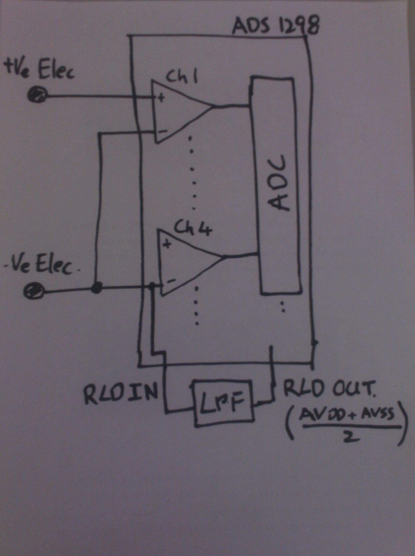
I am currently trying to use an ADS1298 device for a single lead ECG. I have some doubts about how I should configure this device. I tried to configure the device so that Channel 1 is used for the positive electrode, and then I used channel 2 for the negative electrode. I shorted out Channel 1 N and Channel 2 N together, and also connected Channel 2N to RLD.

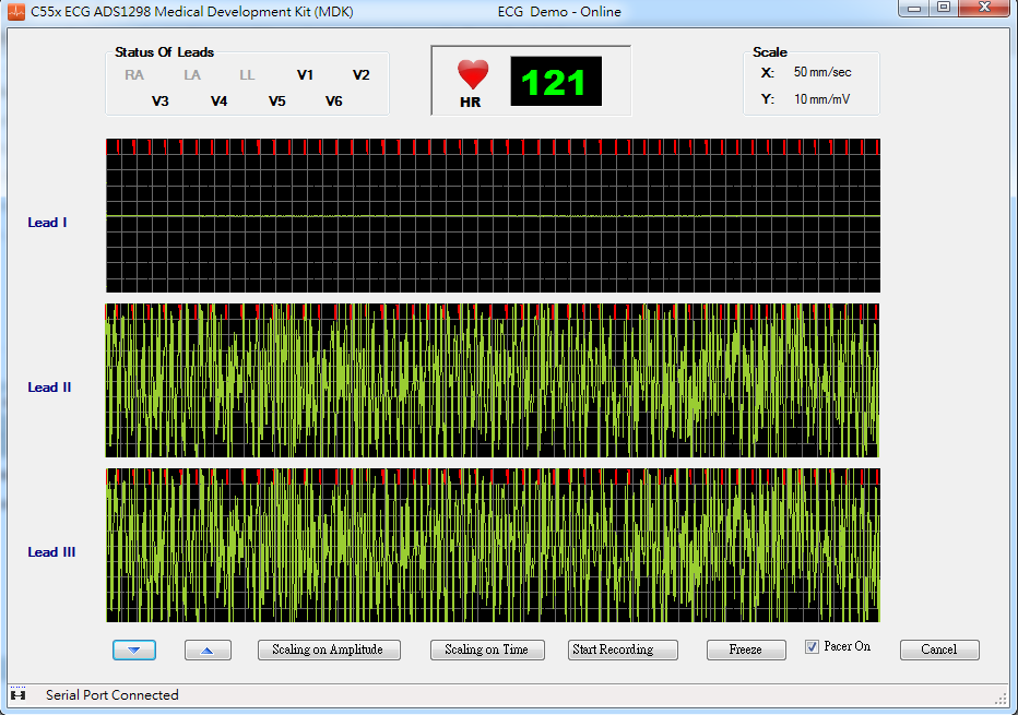
This means that channel 1 P is connected to an electrode and Channel 1 N is at RLD (where RLD is supposed to be (AVDD + AVSS)/2). However, when I output the readings, the output oscillates between positive and negative values, even if the input does not change significantly. My suspicion is that the inputs are drifting, thus resulting in an unpredictable output.

Anybody has any suggestions? Is there any way how I can configure the ADS1298 to use only a single channel for a single lead ECG?


Thanks in advance!


Simon

  • Simon,

    Can you give us a schematic and capture of the waveforms you're describing?

  • Hi Kevin,

    Attached please find a simple schematic:

    Below also find the values of the configuration registers:

    //CONFIG1 0x0001

    0x0086,

    //0x0082,

    //CONFIG2

    0x0010,

    //CONFIG3

    0x00CD,

    //0x00DC,

    //LOFF

    0x0003,

    //CH1SET

    0x0000,

    //CH2SET

    0x0080,

    //CH3SET

    0x0080,

    //CH4SET

    0x0007,

    //CH5SET

    0x0080,

    //CH6SET

    0x0080,

    //CH7SET

    0x0080,

    //CH8SET

    0x0080,

    //RLDSENSP (default)

    0x0000,

    //RLDSENSM (default)

    0x0000,

    //LOFF_SENSP

    0x00FF,

    //LOFF_SENSM

    0x0002,

    //

    //LOFF_FLIP (default)

    0x0000,

    //LOFF_STATP (Read only)

    0x0000,

    //LOFF_STATM (Read only)

    0x0003,

    //GPIO

    0x0000,

    //PACE (default)

    0x0000,

    //RESP (default)

    0x0000,

    //CONFIG4

    0x0002,

    //WCT1

    0x0008,

    //WCT2

    0x0000

    As you could notice from the figure above, the circuit configuration was very simple. Is there a better configuration of ADS1298 for single lead ECG?


    Thanks in advance,

    Simon

  • Hi Simon,

    From a hardware perspective, that is not generally the way to configure the circuit for single lead ECG. The ECG signal read back from the body is a differential signal, so you will want to tie to two electrodes to the (+) and (-) of one of the eight channels from the ADS1298. You will also want to connect the inputs to the RLD through high impedance resistors to set the operating point. Attached is a diagram showing a typical connection to get you on the right track.

    Regards,

    Tony Calabria

  • Dear Tom,

    your diagram is as follow:

    I want electrodes are LA and RA,

    RLD is RLDout? or RLDin ? or RLDinv ? or RLDref?

    and where should I insert a resistance(10M) in my circuit?

  • Hi Yuan-Heng,

    The 10M ohm series resistance comes from RLDout but you need to first close the feedback loop around the internal RLD amplifier as shown in Figure 61.

    Regards,

    Tony Calabria

  •  d

    As follow your idea , right?

    and I set channel 3(lead II) as single lead.

    RLDSP and RLDSN are 0x04,

    WREG CONFIG3 b’x1xx 1100 // Turn on RLD amplifier, set internal RLDREF voltage,

    Could RL  not connect ?

    I still unknow RLD circuit's work principle.


  • Hi Yuan-Heng,

    The 10 Mohm resistors connection are shown correctly in your diagram.

    How the RLD circuit works in principal -

    Typical 3 electrode ECG requires the RLD electrode to bias the patent within range of the converter. Without the RLD electrode, the common mode mode from the patient will float. This will cause the input signal will float in and out of the input range of the converter causing the internal PGA to rail. Additionally, the common mode point from the patient may pick up additional 50/60Hz noise if not biased properly causing noisy results.

    Since you do not want to use a third electrode, you have to bias the inputs in other ways. One way to do this is to use high impedance resistors to bias the inputs within range using the RLD voltage (set at the midpoint between the supplies).

    Regards,

    Tony Calabria

  • Thank you for your teaching ,

    I got it !

    I have a question,

    so RLDout is RLDamp's out?

    and RLDamp's input are RLDref(+) and RLDSN(SP)(-),

    if I connect 10M resistor ,the RL electrode is useless?

    I can just two electrode ,right?

    so RLDin is not necessary ,right?

  • so RLDout is RLDamp's out? Yes

    and RLDamp's input are RLDref(+) and RLDSN(SP)(-),

    if I connect 10M resistor ,the RL electrode is useless? Yes

    I can just two electrode ,right? Yes

    so RLDin is not necessary ,right? Yes

    Regards,

    Tony Calabria

  • if I add the other channel signal,

    I have to add 10M resistance on this channel?

    and I have other question is as follow when I measure signal,

    what happened? thanks 

    the red part is what?

  • Hi Yuan-Heng,

    Your results appear very noisy telling me there must be something that is not connected properly. You will need some digital filtering to remove the 50/60Hz noise components as well as baseline wander and high frequency components. Could you send me a schematic of your circuit as well as a register dump in a table showing me your register settings.

    Thanks,

    Tony

  • could I ask you about the ECG project with ADS1298 & TMS320C5515 's source code?

    my ADS1298 reg setting:

    //Write register opcode1
    0x0041,
    //Write register opcode2
    0x0018,
    //CONFIG1 0x0001
    0x0082,
    //CONFIG2
    0x0010,
    //CONFIG3 1101 1100
    0x00DC,
    //LOFF
    0x0003,
    //CH1SET (PGA gain = 6)
    0x0000,
    //CH2SET (PGA gain = 6)
    0x0040,
    //CH3SET (PGA gain = 6)
    0x0060,
    //CH4SET (PGA gain = 6)
    0x0000,
    //CH5SET (PGA gain = 6)
    0x0000,
    //CH6SET (PGA gain = 6)
    0x0000,
    //CH7SET (PGA gain = 6)
    0x0000,
    //CH8SET (PGA gain = 6)
    0x0000,
    //RLDSENSP (default)
    0x0004,
    //RLDSENSN (default)
    0x0004,
    //LOFF_SENSP
    0x00FF,
    //LOFF_SENSN
    0x0002,
    //LOFF_FLIP (default)
    0x0000,
    //LOFF_STATP (Read only)
    0x0000,
    //LOFF_STATM (Read only)
    0x0003,
    //GPIO
    0x0000,
    //PACE (default)
    0x0000,
    //RESP (default)
    0x0000,
    //CONFIG4
    0x0002,
    //WCT1
    0x000A,
    //WCT2
    0x00E3,

  • So far,

    I can't measure signal correctly sometimes.

    But I already connected 10M resistance to where I should connect.

    After My hand contacted 10M resistance ,the signal is correct.

    Does the reason that my hand is RL?

    Does the operation point must be give by RLDout?

    Has the other operation point to give?

  • connected resistance must 10M?

    or I can use smaller?

  • please tell me all my questions.

    Thank you.

    And My ADS1298's reg setting is error.

    Please point out and let me know .

    Thank you.

  • Hi Yuan-Heng,

    Answers below -

    Does the reason that my hand is RL?

    Yes, In this specific design, RL is used to bias the inputs

    Does the operation point must be give by RLDout?

    You are biasing the inputs

    Has the other operation point to give?

    I do not know what you are asking here

    connected resistance must 10M?or I can use smaller?

    You can use larger or smaller. This resistor will limit the amount of DC current into the body. There are specifications as to how much current you can have through the body in order to be able to certify the product.

    Regards,

    Tony Calabria

  • So I have to give RL for a bias point ?

    Could I generate a (AVDD + AVSS)/2  from inside ,

    if the answer is yes ,how can I get a ref point ?

    or RL also is give a ref point by power supply?

  • Hi Yuan-Heng,

    The RLDREF_INT bit is what you are looking for to generate (AVDD+AVSS)/2 internally for the RLD. See Figure 61 in the data sheet along with the RLDREF_INT bit in the CONFIG3 Register.

    Regards,

    Tony Calabria

  • Hello,

    I also have a doubt about this...I am using an ADS1298 to implement an AFE for sEMG acquisition. Since I only intend to monitor 2 muscles, I am using only Ch1 and Ch2, so my question is: should I short circuit the other input channels I am not using, or this isn't necessary?

    Thanks in advance!

  • Hi Marcia,

    Tie them to the AVDD supply through a weak pull up resistor. The ADS1292 may be a good fit for you if you are only interested in 2 channels.

    Regards,

    Tony Calabria

  • Thanks for the reply! In fact, I am using ADS1298 because this is the only one I have available. But, should I also connect the respiration circuit to AVDD (since I am not using it)?

    Thank you

  • Hi Marcia,

    The respiration modulation output I would terminate to AVDD through weak pull up resistors as well. They can be left floating as well since they are output pins.

    Regards,

    Tony Calabria

  • Hi Tony

    I am using ADS1291 for a single lead ECG record( copied reference design from the data sheet ), with lead and pad on body the data is not bad, but I have tried use finger with out Gel. almost nothing. I am going to try your suggestion here,  my question is how to optimize the 10M ohm resister to get the strongest noise cancellation.  I notice there are few articles in the precision amplifier Forum suggest a two (three finger) solution. if the signal quality is the first priority, do you think discrete amplifier solution will have better performance then this single chip solution. 

    I think for protection point of view, this 10M resistor can go to as low as 500K, because per 60601 CF grade requirement, the leakage is 10uA. 

    Sincerely,

    David Sun

  • Hi Tony ,

    Thanks For Your Expert Advise.

    We actually are using Internal bias for RLDOUT so Does we need to put 10 M resistor Externally to Bias the RLD?

    Thanks & Regards,

     Hitesh  Barot