Because of the Thanksgiving holiday in the U.S., TI E2E™ design support forum responses may be delayed from November 25 through December 2. Thank you for your patience.

This thread has been locked.

If you have a related question, please click the "Ask a related question" button in the top right corner. The newly created question will be automatically linked to this question.

Unable to connect to the target TMS320f2812

Other Parts Discussed in Thread: TMS320F2812

I am presently using XDS510LC emulator, EVM with TMS320f2812 dsp & CCS  Version: 4.1.0.02006 , it is a code limited free version which I downloaded from the TI account. I have been testing sample programs for a while and now suddenly I am not able to connect to the target. I can launch the TI debugger but not able to connect to the target I get following message.


Error connecting to the target:
Error 0x80000200/-1135
Fatal Error during: OCS,
Unrecoverable emulation error


and following message in console:

C28xx: Error connecting to the target: Error 0x80000200/-1135 Fatal Error during: OCS,  Unrecoverable emulation error


I tried following things

1) Reset DSP

2) Reinstall CCS

3) looking at the reference in this discussion

http://e2e.ti.com/support/microcontrollers/tms320c2000_32-bit_real-time_mcus/f/171/t/21614.aspx

I did following thing

" use an emulator that supports wait-in-reset.  I believe the emulator you are using has this.  It uses the EMU0/EMU1 to hold the device at the reset vector until JTAG takes control.  (in SDconfig, emulator folder, make sure to click on the "Perform C28x style wait-in-reset" box)"

Problem i faced in this step is my SdConfigEx v4 is not working. It is not showing any emulator configuration to select from. So I used SdConfig v3.3 C2000 which i got with my emulator. In Sdconfig v3.3 instead of "Perform C28x style wait-in-reset" box)" there is an option of "Perform C27x style wait-in-reset" box)" so I tried the above suggestion it but the problem persists.


for as second suggestion

"2) use the "check boot mode" option in the boot loader that emulates a "wait-in-reset".   Basically this boot mode keeps the code from running into secure memory until you can connect JTAG."

I dont know what to do. where do i find a boot loader? and how to use check boot mode?


Bottom line is the problem is still persistant and I am stuck up without any solution. Any suggestion is welcome only thing is i request a comprehensive solution as I am a beginner in dsp programming.


Thanking you

Girish

  • Hi Girish,

    As per your post,

    I tried following things

    1) Reset DSP

    2) Reinstall CCS

    If your hardware has been working correctly previously, then I doubt that the problem exists in your boot mode settings or other options listed in point 3

    I think the emulator drivers might have been corrupted. Hence, the message "Unrecoverable emulation error"

    Can you try reinstalling the drivers too. Before that I would suggest that you clean up your registry of previous instances of emulator/CCS. Corrupt registry entries can also result in such errors.

    Hope this helps.

    Regards,

    Sid


  • I have reinstalled the drivers as well. Regarding the cleaning up the registry can you please elaborate how to do it? Because i am  not able to connect to the target.

  • Grish,

    A few debug ideas:

    • If this is a device in a socket, make sure the device hasn't come loose or moved around.
    • Can you see the XCLKOUT pin toggle using a scope?
    • Check power/ground using a multimeter.

    -Lori


  • 1) it is not a socket device.

    2) I checked out XCLKOUT pin in scope......it is giving a signal output of 14 Mhz (clocks actual o/p is 150 Mhz)

    3) ground 23  to pin 21 is 5 v, and ground 23 to pin 22 is 3.3 v as it should be

  • Hi Girish,

    To clean the registry, go to Start Menu -> Run

    Type regedit. This will open all registry entries. You need administrative privileges here. Try searching for previous instances of the driver by searching using Ctrl-F.

    If all the previous instances still exist, then delete them.

    If, as you suggest, the problem is not in hardware, then this could well be the issue.

    Regards,

    Sid

  • Girish Yajurvedi said:

    2) I checked out XCLKOUT pin in scope......it is giving a signal output of 14 Mhz (clocks actual o/p is 150 Mhz)

    Grish,

    Is there some code in the flash that is configuring the clocks differently then default? By default SYSCLKOUT is the input clock /2 and then XCLKOUT is SYSCLKOUT /4.  What is the input clock on the board?

    Girish Yajurvedi said:
    3) ground 23  to pin 21 is 5 v, and ground 23 to pin 22 is 3.3 v as it should be

    I'm unclear what "ground 23 to pin 21 is 5v" means.

    My first concern is there are no 5v pins on a 281x.  

    Pins 21 and 23 are not  VSS or VDD pins on either the PGF or PBK package.  Can you clarify?  Which package are you using?

    Some other questions:

    • Is this a TI board or eZdsp or custom board? 
    • Have you ever been able to connect to the device?  or is it a new issue?
    • Can you check that VDD is 1.8 or 1.9 (should be 1.9 if you will operate at 150Mhz)

    Thank you

    Lori


  • "Is there some code in the flash that is configuring the clocks differently then default? By default SYSCLKOUT is the input clock /2 and then XCLKOUT is SYSCLKOUT /4.  What is the input clock on the board?"

    1)No I just used EVA to configure PWM outputs based on sample program. Input clock on the board is 150Mhz according to the manufacturers documents. like as follows.

    EvaRegs.T1PR = 3750;       
       EvaRegs.T1CMPR = 1500;     
       EvaRegs.T1CNT = 0x0000;  ..... continues


    2)

    "I'm unclear what "ground 23 to pin 21 is 5v" means.

    My first concern is there are no 5v pins on a 281x.  

    Pins 21 and 23 are not  VSS or VDD pins on either the PGF or PBK package.  Can you clarify?  Which package are you using?"


    I am sorry for creating confusion, those were not the pins of dsp, but Pin outputs made available from the board. I am not able to specify the package, but it is a board made by third party (GAO TEK).Here is the link for that board details

    http://www.gaotek.com/index.php?main_page=product_info&cPath=118_17&products_id=86


    3)

    • Can you check that VDD is 1.8 or 1.9 (should be 1.9 if you will operate at 150Mhz)-----Since it is a PCB I dont have access to VDD pin.  But the document mentions it as 1.8v                     
    • "Have you ever been able to connect to the device?  or is it a new issue?" ---------Yes I have been able to connect to the board without any issues. it is a recent problem

     I am sending the circuit diagram for further clarification.


    Lastly I noticed that there is  heating of DSP Chip along with other chips on the board. Is it a hardware issue?

    EVM2812Principles.pdf
  •  

    Problem Faced:   I am trying to connect to an TMSF2812 with an XDS510LC emulator. After starting CCS v 4.1.0.02006, I am able to Launch Ti debugger but when I  click "debug" and I get "Error connecting to the target" and the DSP chip on the board gets really hot when power is supplied.

    Error connecting to the target:

    Error 0x80000200/-1041 Fatal Error during:

    OCS,  Device driver: Problem with the Emulation Controller. It is recommended to RESET EMULATOR.  This will disconnect each  target from the emulator.  The targets should then be power cycled or hard reset followed by an emureset and reconnect to each target.


    Set up details:

      1. CCS Version: Version: 4.1.0.02006
      2. CCS Installation directory: C:\Program Files (x86)\Texas Instruments\ccsv4
      3. Chip Part Number and revision:tms320f2812pgfacg-86atokw  
      4. Target Board Manufacturer:Gao Tek
      5. Target board part #: SY-MCK2812HV SL V1
      6. Target connector used:   14 pin TI JTAG
      7. Host Operating System:Windows 7
      8. Host Operating System bits (32-bit or 64-bit): 64 bits
      9. Emulator Board Manufacturer: Spectrum digital XDS510 LC, 14 pin JTAG
      10. XCLKOUT if now between 7-8 Mhz (I am using a 150 Mhz clock crystal and there is no scaling down of the freq in program)

    Secondly I am sending following files in a zip folder for better idea of the problem I am facing:

    1) Eclipse Error Logs:  "errors.log"

    2)Debug server logging: "GIRISH-PC.LOG"

    3) Target configuration: "NewTargetConfiguration.ccxml"

    4)Setup configuration after fault: "sdopts.cfg"

    5) Screen shot of the error: screenshot.doc

    6) some documents related to the board:  file Board


    I request you to kindly guide me as to whether it is a software bug or issue with hardware namely DSP board or emulator.


    Girish


    New Compressed (zipped) Folder.zip
  • I didn't realize you are using spectrum digital. Please run the tests from here: http://tiexpressdsp.com/index.php/Debugging_JTAG_Connectivity_Problems#Using_SDConfig_to_test_JTAG_connections
  • @ Steve

    As I mentioned in my previous post for some reason my sdconfig is not showing the output of the test, neverthless i did dbgjtag test and I am getting following error.

    This error is generated by TI's USCIF driver

    The value is '-141' <0Xffffff73>

    the title is 'SC_ERR_KNL_OPEN'

    the explanation is:

    This utility has failed to open its kernel mode driver

    Either it has been disabled or an install/un-install failed


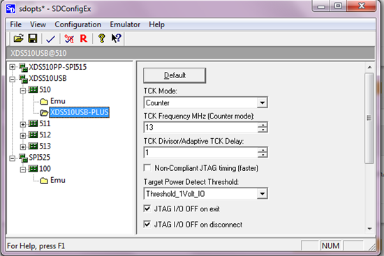
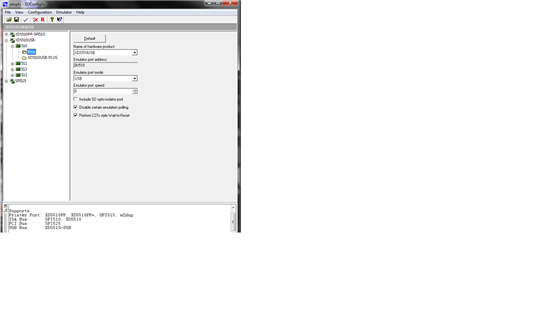
    Secondly my SDConfigEx looks like this as i said the output window is absent I dont know what is the issue. I tried the view option but the output is not displayed, can you also suggest something for this as well?


    Girish


  • Hi Girish,

    For the second question of the missing window in view, I have seen a practical solution which might not be logically true but it works certainly.

    I login with my user privileges, then right-click on SDConfig and select  "Run As"

    Then enter administrator password, so that the program runs on local machine with administrative privileges.

    Not sure what the logic behind this or whether there is any problem with my PC, but this certainly works for me always.

    Hope this helps.

    "

    This utility has failed to open its kernel mode driver

    Either it has been disabled or an install/un-install failed"

    Somehow this still appears to be some registry related issue, though others may have some other suggestions.

    Regards,

    Sid

  • @ Sid,

    Thanks your suggestion about the window was correct the problem was solved.


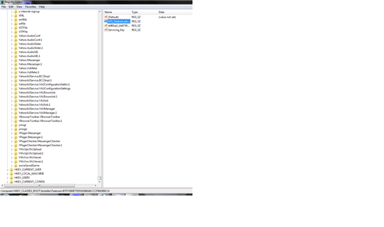
    Secondly I did try to clean up registry but u asked " Try searching for previous instances of the driver by searching using Ctrl-F."

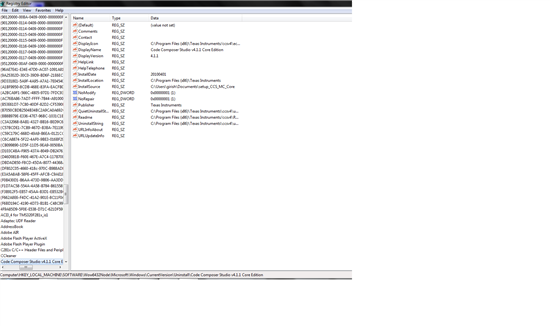
    I did search the files related to the driver for the emulator which is named as "amd64" which is the driver file for emulator & "code composer studio" I got following as the search result.


    So should I delete all the search results or not? am I doing a right search?


    The above one is the search result for code composer studio and the first one was for amd64.


    Girish

  • Hi Girish,

    I suggest you try one section at a time. And dont necessarily use the emulator driver name as the keyword.

    You can use some other popular keyowrds related to emulator like say "SDConfig","xds510" ,etc.

    Some corrupt instances containing these keywords may exist. Delete them one at a time, and try running SDConfig

    Maybe a previous corrupt instance is responsible, though it is difficult to point out which one.

    If all these fail, try deleting CCS related instances as well.

    Hope this gives you a solution.

    Regards,

    Sid

  • @ Sid,


    I tried doing amd64, sdconfig, xds510 and code composer studio at last but problem seems to be persistant.

    Following are the sdconfig test results, it mentions IR scan test failed. I tried to find out what could be corrective/diagnosis for this test failure but I couldnt find anything conclusive. I am looking for someone's input

    setting is as follows:


    Configuration verify

     Spectrum Digital Configuration and Diagnostic Utility

    Supports:

    Printer Port: XDS510PP, XDS510PP+, SPI515, eZdsp

    ISA Bus:      SPI510, XDS510

    PCI Bus:      SPI525

    USB Bus:      XDS510-USB


    ** Using emulation application from directory c:\program files (x86)\texas instruments\ccsv4\emulation\drivers

    ** Checking for a valid emulator/eZdsp


      $$ You are connected to:

      $$ EmuProductName=XDS510USB

      $$ EmuPortAddr=0x510

      $$ EmuPortMode=USB

      $$ ProductId=510

      $$ ProductVersion=84


    Emulator TEST:


    ** Using emulation application from directory c:\program files (x86)\texas instruments\ccsv4\emulation\drivers

    ** Checking for a valid emulator/eZdsp


      $$ You are connected to:

      $$ EmuProductName=XDS510USB

      $$ EmuPortAddr=0x510

      $$ EmuPortMode=USB

      $$ ProductId=510

      $$ ProductVersion=84


    ** Checking emulator/eZdsp scan connection


    ** Emulator Test **


     $$ EmuProductName=XDS510USB


     $$ EmuPortAddr=0x510


     $$ EmuPortMode=USB


     $$ ProductId=510


     $$ ProductVersion=84


     ** Emulator Scan Test


    ERROR >> JTAG IR scan test failed


      >> Check power to your emulator/eZdsp

      >> Then check your port mode/address

    EMULATOR RESET:

     ** Using emulation application from directory c:\program files (x86)\texas instruments\ccsv4\emulation\drivers

     **Emulator is reset


    SCAN PATTERN TEST

    ** Checking for a valid emulator/eZdsp

    ** Running diagnostic scan on EmuProductName=XDS510USB


    ** Checking emulator/eZdsp scan connection


    ERROR >> Failed IR length test


    ERROR >> Diagnostic scan error


    Performed 1 test loops with 1 errors.


    SCAN VERIFY:

    ** Checking for a valid emulator/eZdsp

    ** Running diagnostic scan on EmuProductName=XDS510USB

     ** Checking emulator/eZdsp scan connection


    Girish

  • Hi Girish,

    Can I ask why you are getting different errors at different instances of calling SDCOnfig?

    The registry clean option was for the kernel related error you posted before.

    JTAG IR Scan Test Failed may be related to a faulty emulator cable or EVM related error.

    If you have another board, can you confirm that emulator is working and the cable isnt faulty?

    Regards,

    Sid

  • sid,

    The previous test I did was with "USCIF" driver test because at that time my sdconfig wasnt working. I did change the cable but the problem persists, unfortunately I dont have a different board to make sure that emulator isnt faulty. I asked the board manufacturer regarding the heating problem of the dsp chip he said it is nothing unusual and it could be problem of emulator.


    Girish

  • If the JTAG tests are failing in SDconfig, it's likely that there is something wrong with the JTAG connection. If you can test your emulator against a known working card, we can eliminate the emulator as the problem.

    Did you mention that you were using a time limited version of CCS?

  • Steve


    I am using a "code limited" version of ccs.  The issue is I have just one evm and just one emulator and I am trying to figure out how to conclude this one without have to spend extra. I might have a tough time ahead  convincing my department about spending more on this project. I have already discussed the issues with both board manufacturer and the emulator manufacturer both are suggesting me to test either with different emulator or a different board.

    Thank you for your support though.


    Girish

  • Hi Girish,

    If you dont have another emulator or EVM at hand, then I suggest you try to debug the problem to find whether the EVM or emulator is faulty.

    You already have SDConfig at hand which has something similar to a "Continuous Scan mode", this means it sens a continuous stream of 1's and 0's over the JTAG chain over TDI and receives it over TDO.

    So, I suggest you take an oscilloscope and manually check the waveforms, once with the Emulator alone and the other time with Emulator connected to EVM..

    The faulty signals could be TDI, TDO, TCLK or TRST. You need to determine which one is not responding.

    Any of these signals not working can cause the SCAN test to fail. Check out the signals on the CRO, you might reach a conclusion yourself.

    Regards,

    Sid

  • That is a great suggestion Sid. Basically putting in continuous scan mode with a known bit patter and using a scope to probe tdi/tdo/tms/tck at the pins of the device will tell you a lot about the evm.

  • @ Sid & Steve,


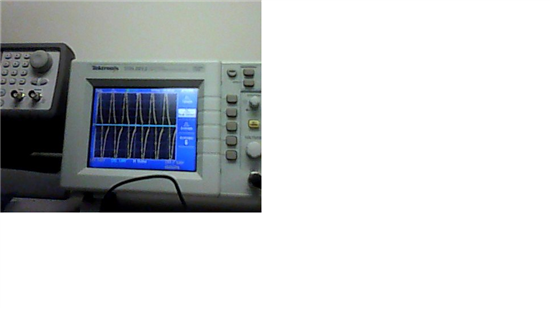
    I observed the waveform output of the EVM JTAG port without emulator connected to it for pins TDI(3) TDO(7) TRST bar(2) and TCK(11), I am getting the following waveform

    Only thing I would like to mention is that the V/divisions was 5v and I am getting these big clock pulses which measure Peak to peak as 42 v. So definitely EVM is problem.

    But the main concerned is that I also tried to check the emulator (by inserting a wire in its port at respective pins) with sdconfig and scan mode on, I am not getting any output waveform at any of the pins. So I am worried as to has these pulses damaged the emulator as well??


    Girish

  • Not sure what would happen to the emulator. Might want to check with Spectrum Digital on that.

  • Hi Girish,

    The fact that you observe Clk pulse peak to peak as 42V is certainly unusual.

    Have you checked that the probe isnt kept at 1X and CRO setting is at 10X or vice versa? This can cause the amplitude displayed to be 10 times the actual amplitude.

    Also, check that the GND terminal you are using as reference is not faulty.

    Regards,

    Sid


  • Sid,

    I double checked all the setting everything seems right.

    Just as a quick question what kind of output waveform should i expect at the scan test from emulator pins. I am not getting any 5 v waveform from the pins of emulator. I just plugged in a wire inside the emulator port and connected them to cro. I am afraid those pulsed might have harmed the emulator as well.


    Girish

  • Hi Girish,

    For the scan test, you should be getting a 1010... pulse on TDI coming from the emulator, TCK should be a continuous clock pulse at the frequency at which the emulator is set to operate and TDO should be a 1010 pulse returning from the DSP processor.

    Maybe you can open up the emulator and try to check the emulator waveforms at the IC level, because as I said before the cable might be faulty or loosely connected. You can check the continuity as well from the emulator to your connector on the EVM.

    Can you check that the probe is fine by checking some other signals on board. As I said, the reference GND that you are using maybe noisy too, though 42V seems a little unrealistic for a 'noisy' signal.

    Regards,

    Sid

  • Hi, I get the same problem with my DSP today. There is any solution to this problem??... I need to change the DSP chip??

    I can´t run SdConfigEx, and my Code Composer (3.1), just hang up when I try to connect the ezDSP.


    Thanks a lot!!


    gianpero

  • Hi gianpero,

    What do you mean by "I cant run SdConfigex". does it give you any error?

    When you say you have same problem, are you using emulator and/or board for first time or it has suddenly become non-functional?

    And are you seeing 42V clk pulses as suggested in above posts?

    Regards,

    Sid

  • Hi, 

    I couldn't test the CLK yet, The only symptom is the DSP chip get relly hot when I plug the ezdsp to the Main Power. 

    am gonna teste the clock and try again to run SdConfigex.


  • Hi,

    Try checking the voltages on board. Possibility of an on-board short might exist.

    Also, which emulator are you using? XDS510?

    Regards,

    Sid

  • Hi, 

    XCLKOUT is in 3 V at 3 MHz

    The oscilator of the ezDSP is in 30Mhz as should be

    The CCS, give me the following error:

    "Failed Software Reset

    Error 0x00000024/-1147

    Error during: Register, Execution.

    It appears that the target is being held in reset. If this is a multi-core system, the master CPU may not be releasing the DSP from the reset.

    Please check your configuration in CSSetup and/or your GEL file to ensure that nothing is blocking the DSP from being released from reset."

    The last project I load in the CPU, has the watchDog disable.

    Thanks


  • Hi,

    If you are using standard gel file for arm-DaVinci then it does not keep the DSP in reset. Which GEL file are you using? Can you post it here

    Also, this problem could arise due to a corrupt session of the emulator which can cause DSP to be held in reset.

    Since you say you have been able to load a program earlier in the CPU, i suggest you terminate the present session, build a new one and retry.

    Also, if possible , try cleaning the registry off instances of previous sessions

    Regards,

    Sid