This thread has been locked.

If you have a related question, please click the "Ask a related question" button in the top right corner. The newly created question will be automatically linked to this question.

SPI COMMUNICATION

Other Parts Discussed in Thread: TMS320DM6437

Hello,

 I tried to establish an SPI communication between EVM TMS320DM6437 (slave) and a module CHEETAH (master).

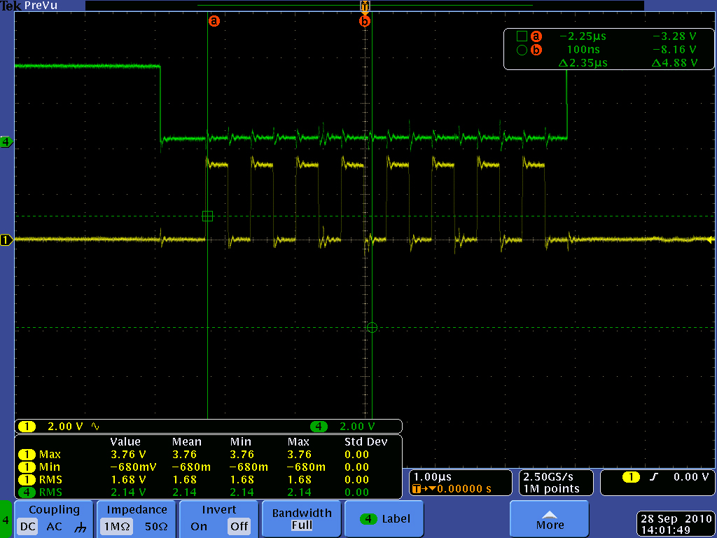
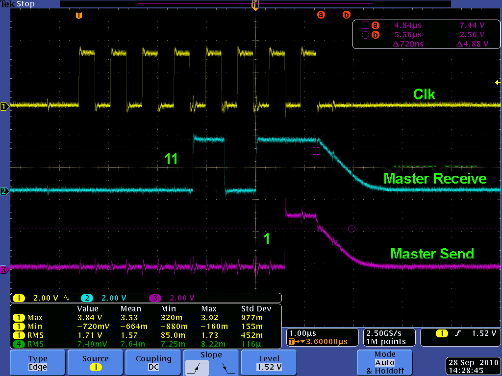
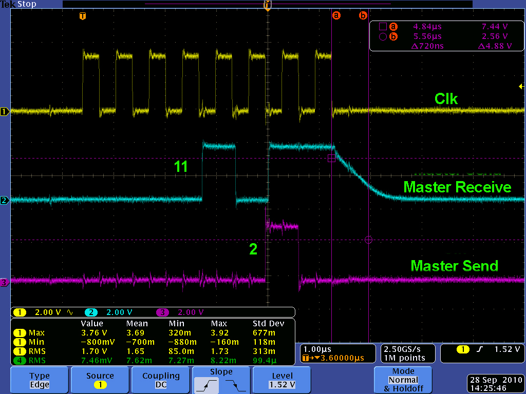
For the packets transmitted from the CHEETAH there are no problem. But I have a small problem with the two first packets sent from the DSP because the first packet is repeated twice then the transmission become correct.

I don't know what could be the problem?

Also, I found a problem in the configuration of Clock stop mode since I configured the EVM in Clock stop mode 0 (CLKSTP = 10b et CLKXP = 0).
On the other hand, to have the correct transmission of packets the CHEETAH must be configured in Clock stop mode 1, I cheked the other modes but the value of packets exchanged was wrong.


Is there an explication for this?

Any suggestion would be appreciated.


  • Hello,

    I am not sure what you mean by "because the first packet is repeated twice then the tranmission become correct"?

    Normally, you would need to set up the EDMA first (if you use the EDMA to write the data into the DXR) and then take McBSP out of reset. If you use the CPU to write the data into the DXR then you need to take the McBSP out of reset, wait for serial clocks then write the transmit data into the DXR. Make sure the initialization sequence is followed correctly. It is documented in the user guide.

    Regarding to the Clock Stop mode 0 vs. 1, you would need to make sure the transmitter/receiver drives/samples transmit/receive data properly with respect of the serial clock. For example, if the transmitter drives the transmit data on on the rising edge of clock, you would configure the receiver to sample the receive data on the falling edge of the clock and vice versa.

    Thanks.  

  • Hello,

    The 2 first packets sent from EVM to CHEETAH are the same which means :

    I have 20 packets that I have sent from EVM to CHEETAH their length is 32 bits 7C12AB64; 45AE19B3; 54AEFA10; CA123490.....

    When the communication between the two devices is established the packet sent from EVM to CHEETAH are like this:

    7C12AB64; 7C12AB64;45AE19B3; 54AEFA10;CA123490 ...The first packet is repeated twice.

    I modified the code many times but without result.

    Speaking about the Clock stop mode I mean that I configured my EVM with mode 0.

    According to CHEETAH I cheked the 4 configuration mode (mode 0; mode 1; mode 2 and mode 3) the result that only mode 1 for the CHEETAH provided me the desired communication. Why this happened?

    Regards,


  • Hello,

    I cannot think of anything that can make the EVM to send the same word out twice except in the case of the data written into the DXR too late, i.e. there is a new frame and the new data is not written into the DXR in time. You might want to check the DXR load mechanism at the start.

    I am not familiar with the Cheetah module so I cannot comment further. It would be helpful to discuss if you can send the waveforms of the EVM transmit/receive and the Cheetah in the working case.

    Thanks and regards.  

  • Hello,

    I thank you for your stand with me.

    Now,I want to see the problem with myself.

    May be I will post you the next week.

    Regards,


  • Hi,


    I am also facing the same problem.

    I am using two 6437 EVM boards. One master and one slave.

    seding data 1 to 10 from Masterto slave.

    receing 11 to 10 from Slave to Master.


    Slave to master is correct. Master to slave, First byte is getting received twice.

    Please check and advice me.


    Master to Slave Slave to Master
    1,2,3,4,5,6,7,8,9,10 11,12,13,14,15,16,17,18,19,20
    Master Slave
    Byte Send: 1  Byte Send: 11 
    Byte Receive: 11  Byte Receive: 1 
    Byte Send: 2  Byte Send: 12 
    Byte Receive: 11  Byte Receive: 2 
    Byte Send: 3  Byte Send: 13 
    Byte Receive: 12  Byte Receive: 3 
    Byte Send: 4  Byte Send: 14 
    Byte Receive: 13  Byte Receive: 4 
    Byte Send: 5  Byte Send: 15 
    Byte Receive: 14  Byte Receive: 5 
    Byte Send: 6  Byte Send: 16 
    Byte Receive: 15  Byte Receive: 6 
    Byte Send: 7  Byte Send: 17 
    Byte Receive: 16  Byte Receive: 7 
    Byte Send: 8  Byte Send: 18 
    Byte Receive: 17  Byte Receive: 8 
    Byte Send: 9  Byte Send: 19 
    Byte Receive: 18  Byte Receive: 9 
    Byte Send: 10  Byte Send: 20 
    Byte Receive: 19  Byte Receive: 10 


  • Hi,

    You said the slave is correct then I assume it is what you see on the pins. It seems to me something is not right with the software reading the DRR for the initial receive data. Is it a CPU read or EDMA for the receiver on the master?  Are you using TI driver software?

    Thanks,

    Tai Nguyen

  • Hi,


    Thank you for your reply.

    I am not using TI driver software.

    I am using CSL.  SPI 8 bit is configured. Master and Slave configuration is done according to the McBSP document.

    It is CPU read.

    This is my send receive function. Used the same function in Master and Slave side.

    Please check.

    unsigned long SPISendReceive ( unsigned long Send )
    {
        unsigned long Recv;

        //poll transmitter is ready
        while(CSL_FEXT(mcbsp0Regs->SPCR,MCBSP_SPCR_XRDY)
            != CSL_MCBSP_SPCR_XRDY_YES);

        //write to transmit register
        mcbsp0Regs->DXR = Send;

        //poll receiver is ready
        while(CSL_FEXT(mcbsp0Regs->SPCR,MCBSP_SPCR_RRDY)
            != CSL_MCBSP_SPCR_RRDY_YES);

        //read receive register
        Recv = mcbsp0Regs->DRR;

        return ( Recv );
    }


    Thank you,

    Lijesh

  • Hi Lijesh,

    I don't see anything wrong with your code. Do you see the slave sends the data "11" twice? Do you have a common ground for the two EVMs? Do you take the slave out of reset first? If not change it and see if it makes anything different.

    Thanks.

    -Tai

  •  

    Hi,


    Thank you for your time.

    Slave sends 11 only once. But Master side it is received twice and all the succeeding bytes are shifted.

    I am sending these data in a loop. So once it finish sending 1-10 and 11-20 it sends again.

    Byte Send: 1  Byte Send: 11 
    Byte Receive: 11  Byte Receive: 1 
    Byte Send: 2  Byte Send: 12 
    Byte Receive: 11  Byte Receive: 2 

    So the next iteration I get like this.

    Byte Send: 1  Byte Send: 11 
    Byte Receive: 20
    Byte Receive: 1 
    Byte Send: 2  Byte Send: 12 
    Byte Receive: 11  Byte Receive: 2 


    This is my Slave init flow

    Frame sync reset,Transmitter reset,Receiver reset,SRGR reset

    Serial port control register SPCR  Configuration (In SPI mode, data sampled on rising edge with delay  )  
                    
    Pin control register ( external frame sync  Trans clock mode  active low)

    Sample rate generator SRGR ( internal clock, clock divider value 1)
       
    Receive control register  (Receive word 8bit )
    Transmit control register (Trans word 8bit)
                   

    SRGR out of reset
        Delay
    Receiver enable
    Transmitter enable
       Delay
    Enable frame sync

    The diagrams are attached.

    1. Clk and Chip Select


    2. Master-Slave 11 and 1

    3.Master-Slave 11 and 2


    When 1 and 2 is send from the master it receives 11 from the slave.

    Thanks


    Lijesh

  • Hi Lijesh,

    It looks like to me the slave sends the first data out twice from start. Could it be the writting to the slave DXR is too late for some reason? How fast do the master and slave run? How fast is CLKX? Maybe you need to check at the master/slave synchronization.

    Thanks.

  • Hi,

    I am using same program on the master and slave side.Only difference is master init and slave init configurations.

    Sample rate generator divider value is 31. SPI clock is 1.5MHz.

    The slave side must be the problem. I am able to read EEPROM using the same program, where 6437 is master.


    Thanks

    Lijesh


  • Hi,

    I agree with you that the slave must be the problem. It should not send the first data out twice. The only thing that I can think of is the slave writes the first data (11) into the DRR and then when the clock and frame come from the master, the slave sends the data (11) out. While it sends out the data (11), it has not written data (12) into the DRR, but the frame and clock come again so it sends out the data (11) in the DRR again.

    But then I cannot explain how the slave catches up with master after the second transfer.

    Maybe you are already doing this but I did not see if you had configured the slave transmit clock pin is from external clock.

    Thanks.

    -Tai 

  • Please post your slave code for review.  The repeated data is likely due to a slave transmit underflow.

    When you take the McBSP out of reset you'll immediately get an XRDY event.  Are you servicing this immediately (i.e. before the master actually starts clocking data)?  It seems like you are since you're actually seeing 11 come out first.  If you were not servicing the McBSP immediately then I would expect the first thing transmitted to be whatever you wrote to DXR last during the previous transfer.  Furthermore, since the McBSP is double-buffered after you service XRDY you will get another XRDY event right away.

    To summarize, when the McBSP comes out of reset you will need to do 2 writes to DXR before the master does any transfers.  Hopefully your code is performing those writes and it's keeping track of the buffer correctly (i.e. hopefully the software is not actually writing the same value twice).

  • Hi Brad Griffis,


    Thank you for your reply.


    Please check the code. The same code is used for Master and Slave. Only Init is changed.

    I am using a delay once the McBSP comes out of reset.


    int main ( void )
    {
        //enable mcbsp0 in power and sleep controller
        McBSP0_PwrOn ();

        //test SPI slave mode
        Test_SPI_Slave ();

    }


    void Test_SPI_Slave ( void )
    {
        unsigned long BytestoSend =10;
        char sendbuffer[10]={11,12,13,14,15,16,17,18,19,20};

        SPI_Slave_Init ( SPI_8BIT );

        while(1)
        {
            ReadBytes ( sendbuffer, BytestoSend );

       
            printf("Send \n");
       
        }

    }

    /*****************************************************************************
    ** Function name:        SPI_Slave_Init
    **
    ** Descriptions:        Initialization McBSP0 to bits working mode
    **
    ** parameters:        SPI working bits number
    ** Returned value:        None
    **
    *****************************************************************************/
    void SPI_Slave_Init ( unsigned long Bits )
    {
        unsigned long i;
       
        CSL_FINST(mcbsp0Regs->SPCR,MCBSP_SPCR_FRST,RESET);       //frame sync reset
        CSL_FINST(mcbsp0Regs->SPCR,MCBSP_SPCR_XRST,DISABLE);    //transmitter reset
        CSL_FINST(mcbsp0Regs->SPCR,MCBSP_SPCR_RRST,DISABLE);    //receiver reset
        CSL_FINST(mcbsp0Regs->SPCR,MCBSP_SPCR_GRST,CLKG);      //SRGR reset

        //serial port control register SPCR
        mcbsp0Regs->SPCR = CSL_FMKT(MCBSP_SPCR_CLKSTP,DELAY);    //In SPI mode, data sampled on rising edge with delay    
                    
        //pin control register
        mcbsp0Regs->PCR = CSL_FMKT(MCBSP_PCR_FSXM,EXTERNAL)    //external frame sync
                    | CSL_FMKT(MCBSP_PCR_CLKXM,INPUT)    //trans clock mode
                    | CSL_FMKT(MCBSP_PCR_FSXP,ACTIVELOW);    //active low

        //sample rate generator SRGR
        mcbsp0Regs->SRGR = CSL_FMKT(MCBSP_SRGR_CLKSM,INTERNAL) //internal clock
                    | CSL_FMK(MCBSP_SRGR_CLKGDV,1);      //clock divider value

        switch ( Bits )
        {
            case SPI_8BIT:
                // receive control register               
                mcbsp0Regs->RCR = CSL_FMKT(MCBSP_RCR_RWDLEN1,8BIT);   //receive word 8bit
                //transmit control register
                mcbsp0Regs->XCR = CSL_FMKT(MCBSP_XCR_XWDLEN1,8BIT);   //trans word 8bit
                break;
            case SPI_12BIT:
                // receive control register               
                mcbsp0Regs->RCR = CSL_FMKT(MCBSP_RCR_RWDLEN1,12BIT);   //receive word 12bit
                //transmit control register
                mcbsp0Regs->XCR = CSL_FMKT(MCBSP_XCR_XWDLEN1,12BIT);   //trans word 12bit
                break;
            case SPI_16BIT:
                // receive control register               
                mcbsp0Regs->RCR = CSL_FMKT(MCBSP_RCR_RWDLEN1,16BIT);   //receive word 16bit
                //transmit control register
                mcbsp0Regs->XCR = CSL_FMKT(MCBSP_XCR_XWDLEN1,16BIT);   //trans word 16bit
                break;
            case SPI_20BIT:
                // receive control register               
                mcbsp0Regs->RCR = CSL_FMKT(MCBSP_RCR_RWDLEN1,20BIT);   //receive word 20bit
                //transmit control register
                mcbsp0Regs->XCR = CSL_FMKT(MCBSP_XCR_XWDLEN1,20BIT);   //trans word 20bit
                break;
            case SPI_24BIT:
                // receive control register               
                mcbsp0Regs->RCR = CSL_FMKT(MCBSP_RCR_RWDLEN1,24BIT);   //receive word 24bit
                //transmit control register
                mcbsp0Regs->XCR = CSL_FMKT(MCBSP_XCR_XWDLEN1,24BIT);   //trans word 24bit
                break;
            case SPI_32BIT:
                // receive control register               
                mcbsp0Regs->RCR = CSL_FMKT(MCBSP_RCR_RWDLEN1,32BIT);   //receive word 32bit
                //transmit control register
                mcbsp0Regs->XCR = CSL_FMKT(MCBSP_XCR_XWDLEN1,32BIT);   //trans word 32bit
                break;
            default:;
        }
       
        //start the mcbsp running
        CSL_FINST(mcbsp0Regs->SPCR,MCBSP_SPCR_GRST,CLKG);      //SRGR out of reset
        for ( i = 0; i < 200; i++ ) { i++; }
        CSL_FINST(mcbsp0Regs->SPCR,MCBSP_SPCR_RRST,ENABLE);    //receiver enable
        CSL_FINST(mcbsp0Regs->SPCR,MCBSP_SPCR_XRST,ENABLE);    //transmitter enable
        for ( i = 0; i < 200; i++ ) { i++; }
        CSL_FINST(mcbsp0Regs->SPCR,MCBSP_SPCR_FRST,FSG);       //enable frame sync
    }


    /*****************************************************************************
    ** Function name:        SPISendReceive
    **
    ** Descriptions:        Send & Receive data from SPI
    **
    ** parameters:        Send data
    ** Returned value:        Receive data
    **
    *****************************************************************************/
    unsigned long SPISendReceive ( unsigned long Send )
    {
        unsigned long Recv;

        //poll transmitter ready
        while(CSL_FEXT(mcbsp0Regs->SPCR,MCBSP_SPCR_XRDY)
            != CSL_MCBSP_SPCR_XRDY_YES);

        //write to transmit register
        mcbsp0Regs->DXR = Send;

        //poll receiver is ready
        while(CSL_FEXT(mcbsp0Regs->SPCR,MCBSP_SPCR_RRDY)
            != CSL_MCBSP_SPCR_RRDY_YES);

        //read receive register
        Recv = mcbsp0Regs->DRR;

        return ( Recv );
    }


    /*****************************************************************************
    ** Function name:        ReadBytes
    **

    **
    *****************************************************************************/
    unsigned char ReadBytes ( char * buffer, unsigned long Bytes )
    {
        unsigned long Data;
        int i=0;

        for(i=0; i<Bytes; i++)
        {   
        //Read one byte of data
        Data = SPISendReceive ( buffer[i] );
        printf("Byte Send: %d \n", buffer[i]);
        printf("Byte Receive: %d \n", Data);

    }
    //    return ( Data );
    }


  • Hi Lijesh,

    Thanks for sharing your code. I don't see anything wrong with your code. I think the problem could be that at the beginning, due to the double buffer, the master sends out the first two data too fast that the slave could not put the second data into the slave DXR fast enough, hence it sends out the same data. Can you capture all ten transfers to see if all ten transfers happen equally timewise?

    Thanks,

    Tai 

  • Also, please note that printf() will actually cause the processor to momentarily halt.  In the world of processors operating at hundreds of MHz this sudden halting is for a VERY long time.  This will severely impact real-time performance.  I would definitely remove any printf statements in the midst of the transfers as that will have a major real-time impact.  You could instead send/receive an entire buffer and printf the entire buffer at the end, or perhaps just print a pass/fail message at the end.  It would be much better to use a logic analyzer for this purpose.

  • Hi,

    Thank you for your time.

    I tried reducing master clock speed and giving a delay after each byte send. But there is no change. always the first data is received twice.

    All the 10 transfers happen equally timewise. The next iteration the master sends 1 and receives 20 from the slave.

    i.e. Master first receives 11,11,12...  19 (10 bytes).  So 20 pops out for the next iteration.


    Also tried without printf. But no difference.

    Another interesting thing is if i call SPI_Slave_Init ( SPI_8BIT ) before sending each byte on salve side, I am able to receive data correctly.!!


    unsigned char ReadBytes ( char * buffer, unsigned long Bytes )
    {
        unsigned long Data;
        int i=0;

        for(i=0; i<Bytes; i++)
        {   

    SPI_Slave_Init ( SPI_8BIT ); // This step on slave side solves the issue.
        //Read one byte of data
        Data = SPISendReceive ( buffer[i] );
        printf("Byte Send: %d \n", buffer[i]);
        printf("Byte Receive: %d \n", Data);


    }
    //    return ( Data );
    }


    Actually I dont need to do the complete initialization. These steps are enough.

    Normal 0 false false false EN-US X-NONE ML MicrosoftInternetExplorer4

                    //serial port control register SPCR

                    mcbsp0Regs->SPCR = CSL_FMKT(MCBSP_SPCR_CLKSTP,DELAY);

                    CSL_FINST(mcbsp0Regs->SPCR,MCBSP_SPCR_GRST,CLKG);      //SRGR out of reset

                    for ( i = 0; i < 20; i++ ) { i++; }

                    CSL_FINST(mcbsp0Regs->SPCR,MCBSP_SPCR_RRST,ENABLE);    //receiver enable

                    CSL_FINST(mcbsp0Regs->SPCR,MCBSP_SPCR_XRST,ENABLE);    //transmitter enable

                    for ( i = 0; i < 20; i++ ) { i++; }


    This is not the proper way. It will reduce the through put a lot.


  • Lijesh,

    You get the same data twice in the case of an underflow.  There are a couple ways to overcome the problem.  Basically you need to do TWO writes to DXR at the start of your transfer.  You could do that by choosing either one of these options:

    1. Switch to interrupts.  You will get an XRDY interrupt as soon as you take McBSP out of reset.  After your ISR writes to DXR that data will be immediately shifted into XSR and will generate a 2nd interrupt before you've actually transmitted/received any data. - OR -
    2. Write some additional functions like SpiSendReceiveFirst and SpiSendReceiveLast.  These are the 'special cases'.  For "First" you would do only a write (no read).  For "Last" you would do only a read.

    Best regards,
    Brad

  • Hello Lijesh,

            Can you please put the code which you used for  McBSP0_PwrOn () funciton.

    I guess my power on is not appropirate. Thank you..

  • Hi Kanthi Uppala,

    Please find the function.


    void McBSP0_PwrOn ( void )
    {
     
      CSL_PscRegsOvly pscRegs = (CSL_PscRegsOvly)CSL_PSC_0_REGS;

      // deassert MCBSP0 local PSC reset and set NEXT state to ENABLE
      pscRegs->MDCTL[CSL_PSC_MCBSP0] = CSL_FMKT( PSC_MDCTL_NEXT, ENABLE )
                                     | CSL_FMKT( PSC_MDCTL_LRST, DEASSERT );
     
      //move MCBSP0 PSC to Next state
      pscRegs->PTCMD = CSL_FMKT(  PSC_PTCMD_GO0, SET );
     
      //wait for transition
      while ( CSL_FEXT( pscRegs->MDSTAT[CSL_PSC_MCBSP0], PSC_MDSTAT_STATE )
              != CSL_PSC_MDSTAT_STATE_ENABLE );
     
    }

  • Hello Lijesh,


             For the master configuration...  i have changed the following from ur configuration above..:

    1) FSXM as internal

    2)CLKXM as External

    3)Placed a value of 255 for CLKGDV

    4) Gave a 1bit delay in both XDATDLY & RDATDLY.


    But the master is not sending the right signals... do i need to change any thing else?

  • Hello,

    I am using DM6437 EVM to test SPI communication. I am not using TI driver code but I have modified the McBSP CSL example code for SPI communication.

    To test the SPI communication, I have configured McBSP0 as a SPI master and McBSP1 as a SPI Slave as per the MCBSP user guide SPRU943c. I have also externally connected pins (transmit and receives) between McBSP0 and McBSP1 as per SPRU943c. I have successfully data transfer from McBSP0 (as SPI Master) to McBSP1( as SPI Slave) i.e means data transfer from SPI master to SPI slave. However I could not able to do data transfer from McBSP1 (as a SPI slave) to McBSP0 (as a SPI master).  (i.e. data transfer from Slave to master).  I am not able to receive single word at SPI master transmitted from SPI Slave.

    I am trying to send few bytes from SPI slave to SPI master. But SPI master is not able to receive single byte from slave.

    Can anybody please review my code and let me know what should i have to do so Slave can able to tranfer few words to master. 

    /*  ============================================================================
     *   Copyright (c) Texas Instruments Inc 2002, 2003, 2004, 2005, 2006, 2007
     *
     *   Use of this software is controlled by the terms and conditions found
     *   in the license agreement under which this software has been supplied.
     *  ============================================================================
     */
    
    /** ============================================================================
     *   @brief A simple example to demonstrate CSL 3.x MCBSP register layer usage.
     *
     *   @file  mcbsp_example.c
     *
     *   <b> Example Description </b>
     *   @verbatim
         This example configures MCBSP0 in 32 bit loopback mode and uses software 
         polling to transmit and receive 32bit words. Four 32 bit words are 
         transmitted and received and the results are verified.  A pass\fail 
         test status is returned from main.     
         @endverbatim
     *
     *      
     *   <b> Procedure to run the example </b>
     *   @verbatim
         1. Configure the CCS setup to work with the emulator being used
         2. Please refer CCS manual for setup configuration and loading 
            proper GEL file
         3. Launch CCS window
         4. Open project Mcbsp_example.pjt
         5. Build the project and load the .out file of the project.
         @endverbatim
     *
     * =============================================================================
     **/
    
    #include <csl_types.h>
    #include <soc.h>
    #include <c6x.h>
    #include <cslr_sys.h>
    #include <cslr_intc.h>
    #include <cslr_mcbsp.h>
    #include <stdio.h>
    #include <cslr_psc.h>
    
    #define NUM_WORDS   4
    volatile int intFlag=1;
    volatile int intFlag0=1;
    Uint32 transBuff[4] = {0x5A5A5A5A,0x87654321,0x11223344,0x55667788};
    Uint32 trans_val[NUM_WORDS] ;
    Uint32 rec_val[NUM_WORDS] ;
    Uint32 rec_val0[NUM_WORDS] ;
    
    
    static void device_init(void); 
    static void init_mcbsp(void);   
    static int test_mcbsp(void);   
    extern void intcVectorTable(void);
    
    CSL_McbspRegsOvly mcbsp0Regs = (CSL_McbspRegsOvly)CSL_MCBSP_0_REGS;
    CSL_McbspRegsOvly mcbsp1Regs = (CSL_McbspRegsOvly)CSL_MCBSP_1_REGS;
    CSL_IntcRegsOvly intcRegs = (CSL_IntcRegsOvly)CSL_INTC_0_REGS;
    
    int main (void) 
    {
      //enable mcbsp0 in power and sleep controller
      device_init(); 
      
      //setup mcbsp registers and start mcbsp running 
      init_mcbsp();
      
      //test loopback, returns 0 for pass and 1 for fail 
      return(test_mcbsp());
    }
    
    void init_mcbsp(void)
    {
    	int i;
    	//serial port control register SPCR
       CSL_FINST(mcbsp0Regs->SPCR,MCBSP_SPCR_RRST,DISABLE);    		//receiver enable
       CSL_FINST(mcbsp0Regs->SPCR,MCBSP_SPCR_XRST,DISABLE);    		//transmitter enable
       CSL_FINST(mcbsp0Regs->SPCR,MCBSP_SPCR_GRST,RESET);      		//SRGR out of reset
       CSL_FINST(mcbsp0Regs->SPCR,MCBSP_SPCR_FRST,RESET);       	//enable frame sync
    
       //mcbsp0Regs->SPCR = CSL_FMKT(MCBSP_SPCR_DLB,ENABLE);    	   //enable loopback mode
       mcbsp0Regs->SPCR = CSL_FMKT(MCBSP_SPCR_CLKSTP,DELAY);    	   //enable clk stop mode with NODELEY or DELAY
                     
      // receive control register                
      //mcbsp0Regs->RCR = CSL_FMKT(MCBSP_RCR_RWDLEN1,32BIT)   	//receive word 32bit
      //	  	  	  	  	| CSL_FMK(MCBSP_RCR_RFRLEN1,NUM_WORDS);   		//1st Phase frame length RFRLEN1
      //CSL_FINST(mcbsp0Regs->RCR, MCBSP_RCR_RDATDLY,1BIT);    	//receive data delay 1bit
    
      //transmit control register
      mcbsp0Regs->XCR = CSL_FMKT(MCBSP_XCR_XWDLEN1,32BIT)		//trans word 32bit
    				    |CSL_FMK(MCBSP_XCR_XFRLEN1,0);   		//1st Phase frame length XFRLEN1
      CSL_FINST(mcbsp0Regs->XCR, MCBSP_XCR_XDATDLY,1BIT);    	//trans data delay 1bit
    
      
      //sample rate generator SRGR
      mcbsp0Regs->SRGR = CSL_FMKT(MCBSP_SRGR_CLKSM,INTERNAL) 	//internal clock, defualt CLKG
    				  //| CSL_FMKT(MCBSP_SRGR_FSGM,DXR2XSR)     	//(FSGM  = DXR2XSR or FSG, FSX is generated only when DXR to XSR copy)
    				  //| CSL_FMKT(MCBSP_SRGR_GSYNC,FREE)       	//(GSYNC  = FREE or SYNC, Sample rate generator is free running, defualt FREE)
    				  //| CSL_FMKT(MCBSP_SRGR_CLKSP,RISING)     	//(CLKSP  = RISING or FALLING, CLKS polarity is used only when clks are external, defualt RISING )
                      //| CSL_FMK(MCBSP_SRGR_FPER,63)         	//frame period
                      //| CSL_FMK(MCBSP_SRGR_FWID,31)         	//frame width
                      | CSL_FMK(MCBSP_SRGR_CLKGDV,99);      		//clock divider value
    
      mcbsp0Regs->SRGR |= (0 << 31);    	// (GSYNC = 0, Sample rate generator is free running)
      mcbsp0Regs->SRGR |= (0 << 30);    	// (CLKSP = 0, CLKS polarity is used only when clks are external)
      mcbsp0Regs->SRGR |= (0 << 28);    	// (FSGM  = 0, FSX is generated only when DXR to XSR copy)
    
      //pin control register
      mcbsp0Regs->PCR = CSL_FMKT(MCBSP_PCR_FSXM,  INTERNAL)    		//internal frame sync defualt EXTERNAL
    				 //| CSL_FMKT(MCBSP_PCR_FSRM,EXTERNAL)     		//internal fram sync defualt EXTERNAL
                     //| CSL_FMKT(MCBSP_PCR_CLKRM,INPUT)      		//internal fram sync defualt INPUT
                     | CSL_FMKT(MCBSP_PCR_CLKXM,  OUTPUT)     		//trans clock mode
                     | CSL_FMKT(MCBSP_PCR_FSXP,   ACTIVELOW)   		//ACTIVELOW or ACTIVEHIGH, FSX polarity is used only when clks are external, defualt RISING
                     | CSL_FMKT(MCBSP_PCR_CLKXP,  RISING)     		//RISING or FALLING, CLKS polarity is used only when clks are external, defualt RISING
      	  	  	  	 | CSL_FMKT(MCBSP_PCR_SCLKME, NO);       		//sample clock mode selection bit defualt NO, else BCLK to set 1
    
      // McBSP 1 config
    #if 1
      	//serial port control register SPCR
    
        CSL_FINST(mcbsp1Regs->SPCR,MCBSP_SPCR_RRST,DISABLE);     	//receiver enable
        CSL_FINST(mcbsp1Regs->SPCR,MCBSP_SPCR_XRST,DISABLE);     	//transmitter enable
        CSL_FINST(mcbsp1Regs->SPCR,MCBSP_SPCR_GRST,RESET);       	//SRGR out of reset
        CSL_FINST(mcbsp1Regs->SPCR,MCBSP_SPCR_FRST,RESET);       	//enable frame sync
    
        //mcbsp1Regs->SPCR = CSL_FMKT(MCBSP_SPCR_DLB,ENABLE);    	//enable loopback mode
        mcbsp1Regs->SPCR = CSL_FMKT(MCBSP_SPCR_CLKSTP,DELAY);  	//enable clk stop mode with NODELEY or DELAY
    
        // receive control register
        mcbsp1Regs->RCR = CSL_FMKT(MCBSP_RCR_RWDLEN1,32BIT)   		//receive word 32bit
    					  | CSL_FMK(MCBSP_RCR_RFRLEN1,0);   		//1st Phase frame length RFRLEN1
        CSL_FINST(mcbsp1Regs->RCR, MCBSP_RCR_RDATDLY,0BIT);    		//receive data delay 1bit
    
        //transmit control register
        //mcbsp1Regs->XCR = CSL_FMKT(MCBSP_XCR_XWDLEN1,32BIT)	    	//trans word 32bit
    	//				  | CSL_FMK(MCBSP_XCR_XFRLEN1,NUM_WORDS);   		//1st Phase frame length XFRLEN1
        //CSL_FINST(mcbsp1Regs->XCR, MCBSP_XCR_XDATDLY, 0BIT);    	//trans data delay 1bit
    
        //sample rate generator SRGR
        mcbsp1Regs->SRGR = CSL_FMKT(MCBSP_SRGR_CLKSM,INTERNAL) 		//internal clock, defualt CLKG
        				  //| CSL_FMK(MCBSP_SRGR_FSGM,DXR2XSR)     	//(FSGM  = DXR2XSR or FSG, FSX is generated only when DXR to XSR copy)
        				  //| CSL_FMK(MCBSP_SRGR_GSYNC,FREE)       	//(GSYNC  = FREE or SYNC, Sample rate generator is free running, defualt FREE)
        				  //| CSL_FMK(MCBSP_SRGR_CLKSP,RISING)     	//(CLKSP  = RISING or FALLING, CLKS polarity is used only when clks are external, defualt RISING )
                          //| CSL_FMK(MCBSP_SRGR_FPER,63)         	//frame period
                          //| CSL_FMK(MCBSP_SRGR_FWID,31)         	//frame width
                          | CSL_FMK(MCBSP_SRGR_CLKGDV,12);      		//clock divider value
    
    
        //pin control register
        mcbsp1Regs->PCR = CSL_FMKT(MCBSP_PCR_FSXM,  EXTERNAL)    	//internal frame sync defualt EXTERNAL
        				 //| CSL_FMKT(MCBSP_PCR_FSRM,EXTERNAL)     	//internal fram sync defualt EXTERNAL
                         //| CSL_FMKT(MCBSP_PCR_CLKRM,INPUT)      	//internal fram sync defualt INPUT
                         | CSL_FMKT(MCBSP_PCR_CLKXM,  INPUT)     	//trans clock mode
                         | CSL_FMKT(MCBSP_PCR_FSXP,   ACTIVELOW)   	//ACTIVELOW or ACTIVEHIGH, FSX polarity is used only when clks are external, defualt RISING
                         | CSL_FMKT(MCBSP_PCR_CLKXP,  RISING)     	//RISING or FALLING, CLKS polarity is used only when clks are external, defualt RISING
          	  	  	  	 | CSL_FMKT(MCBSP_PCR_SCLKME, NO);       	//sample clock mode selection bit defualt NO, else BCLK to set 1
    
    
        CSL_FINST(mcbsp1Regs->SPCR,MCBSP_SPCR_GRST,CLKG);      //SRGR out of reset
        for ( i = 0; i < 200; i++ ) { i++; }
        CSL_FINST(mcbsp1Regs->SPCR,MCBSP_SPCR_RRST,ENABLE);    //receiver enable
        CSL_FINST(mcbsp1Regs->SPCR,MCBSP_SPCR_XRST,ENABLE);    //transmitter enable
        for ( i = 0; i < 200; i++ ) { i++; }
        CSL_FINST(mcbsp1Regs->SPCR,MCBSP_SPCR_FRST,FSG);       //enable frame sync
    #endif
      //start the mcbsp running
      CSL_FINST(mcbsp0Regs->SPCR,MCBSP_SPCR_GRST,CLKG);      //SRGR out of reset
      for ( i = 0; i < 200; i++ ) { i++; }
      CSL_FINST(mcbsp0Regs->SPCR,MCBSP_SPCR_RRST,ENABLE);    //receiver enable
      CSL_FINST(mcbsp0Regs->SPCR,MCBSP_SPCR_XRST,ENABLE);    //transmitter enable
      for ( i = 0; i < 200; i++ ) { i++; }
      CSL_FINST(mcbsp0Regs->SPCR,MCBSP_SPCR_FRST,FSG);       //enable frame sync
    
    }
    
    int test_mcbsp(void)
    {
        int i;
    
        printf("\nTesting mcbsp loopback SDK\n\n");
    
        // mcbsp 0 transmit and mcbsp 1 receive
        for(i=0;i<NUM_WORDS;i++)
        {
        	trans_val[i] = transBuff[i];
            //poll transmitter ready
            while(CSL_FEXT(mcbsp0Regs->SPCR,MCBSP_SPCR_XRDY)
                 != CSL_MCBSP_SPCR_XRDY_YES);
    
            //write to transmit register
            mcbsp0Regs->DXR = trans_val[i];
    
            //poll receiver is ready
            while(CSL_FEXT(mcbsp1Regs->SPCR,MCBSP_SPCR_RRDY)  != CSL_MCBSP_SPCR_RRDY_YES);
            rec_val[i] = mcbsp1Regs->DRR;
    
        }
    
        //check results
        for(i=0;i<NUM_WORDS;i++)
        {
            if(trans_val[i]==rec_val[i])
                printf("transmit: 0x%x   receive: 0x%x\n",trans_val[i],rec_val[i]);
            else
               {
                 printf(" error\n");
                 printf("\nMCBSP Loopback Test:  FAILED\n");
                 printf("transmit: 0x%x   receive: 0x%x\n",trans_val[i],rec_val[i]);
                 return(1);
               }
        }
    
        // mcbsp 1 transmit and mcbsp 0 receive
        for(i=0;i<NUM_WORDS;i++)
        {
        	rec_val0[i] = 0;
        	trans_val[i] = transBuff[i];
            //poll transmitter ready
            while(CSL_FEXT(mcbsp1Regs->SPCR,MCBSP_SPCR_XRDY)   != CSL_MCBSP_SPCR_XRDY_YES);
    
            //write to transmit register
            mcbsp1Regs->DXR = trans_val[i];
            printf("transmit: 0x%x\n",trans_val[i]);
            //poll receiver is ready
            while(CSL_FEXT(mcbsp0Regs->SPCR,MCBSP_SPCR_RRDY)  != CSL_MCBSP_SPCR_RRDY_YES);
            rec_val0[i] = mcbsp0Regs->DRR;
            printf(" receive: 0x%x\n",rec_val0[i]);
    
    
        }
    
        //check results
        for(i=0;i<NUM_WORDS;i++)
        {
            if(trans_val[i]==rec_val0[i])
                printf("transmit: 0%x   receive: 0x%x\n",trans_val[i],rec_val0[i]);
            else
               {
                 printf(" error\n");
                 printf("\nMCBSP Loopback Test:  FAILED\n");
                 printf("transmit: 0x%x   receive: 0x%x\n",trans_val[i],rec_val0[i]);
                 return(1);
               }
        }
    
        printf("\nMCBSP Loopback Test:  PASSED\n");
        
        return(0);
    }
    
    void device_init(void) 
    {
      
      CSL_PscRegsOvly pscRegs = (CSL_PscRegsOvly)CSL_PSC_0_REGS;
    
      // deassert MCBSP0 local PSC reset and set NEXT state to ENABLE
      pscRegs->MDCTL[CSL_PSC_MCBSP0] = CSL_FMKT( PSC_MDCTL_NEXT, ENABLE )
                                     | CSL_FMKT( PSC_MDCTL_LRST, DEASSERT );
     
      //move MCBSP0 PSC to Next state
      pscRegs->PTCMD = CSL_FMKT(  PSC_PTCMD_GO0, SET );
     
      //wait for transition
      while ( CSL_FEXT( pscRegs->MDSTAT[CSL_PSC_MCBSP0], PSC_MDSTAT_STATE )
              != CSL_PSC_MDSTAT_STATE_ENABLE );
    
    	// deassert MCBSP1 local PSC reset and set NEXT state to ENABLE
    	pscRegs->MDCTL[CSL_PSC_MCBSP1] = CSL_FMKT( PSC_MDCTL_NEXT, ENABLE )
    								   | CSL_FMKT( PSC_MDCTL_LRST, DEASSERT );
    
    	//move MCBSP1 PSC to Next state
    	pscRegs->PTCMD = CSL_FMKT(  PSC_PTCMD_GO0, SET );
    
    	//wait for transition
    	while ( CSL_FEXT( pscRegs->MDSTAT[CSL_PSC_MCBSP1], PSC_MDSTAT_STATE )
    			!= CSL_PSC_MDSTAT_STATE_ENABLE );
    
    }


    I have attached my test code here with.  Please do the needful ASAP.

    P.S.

    EVM DM6437 clock freq 594Mhz,

    MCBSP freq 99MHz,

    SPI Master (Mcbsp0) clock freq 1 MHz, clock divider value 99.

    SPI Slave (Mcbsp1) clock freq 8.25 MHz, clock divider value 12.