This thread has been locked.

If you have a related question, please click the "Ask a related question" button in the top right corner. The newly created question will be automatically linked to this question.

DM6437 Raw capture and color problem

Other Parts Discussed in Thread: CCSTUDIO, TVP5146

Hi,

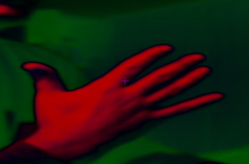
I'm using raw capture example to acquire images from a cmos sensor as some of us suggested. Now I can download the image, but color are incorrect, I have changed sensor settings like shutter row number, Green, Red and Blue Gain, but without results. I set sensor in YUV mode and this the result:

When I put U=V=128 I suppose that the image results in gray scale but it is all black!

What I do wrong? I also notice Vertical row in my image?!

  • I am glad to hear you now get an image from your sensor, I am sure this is something that can be cleaned up in software. Looking at the image initially it looks to me like you are missing the blue channel of a RGB image, but you mention that your sensor can output YUV so I am not sure this makes sense, perhaps it could be a configuration problem on the sensor?

    Is there a public place on the web where the datasheet for your sensor is posted? I am curious about the data formats it is capible of outputting and how much configurability it has, this is probably either a format disagreement somewhere or a bad color space conversion configuration in the sensor.

    I suspect the vertical lines are just another byproduct of the issue that is causing the color problem, if there is a format disagreement it could manifest itself in vertical lines if one side is expecting more bits (per pixel) than the other.

  • Yes,it partially works..... thank you so much for the answers! The sensor is Micron MT9D131, there is limited documentation at Aptina site! It can output:

     RAW Data : 8+2 bit, YUV and RGB (in various format 565 etc..). I set YUV output and I can see that the amount of byte is exactly 480x720x2,(ie: Y0 U0 Y1 V0) and if I change in CCStudio Image Tool one of channels I see one image with 2 sort of small transparent image on it (It seems the typical effect of turning channels in YUV format). I will check if there is Blue Gain disable or something similar? In CDDC configuration I leave :

    static PSP_VPFECcdcConfigParams ccdcParams =
    {
        FVID_CCDC_RAW_FORMAT,                  /* dataFlow  FVID_CCDC_YCBCR_8    FVID_CCDC_RAW_FORMAT*/
        FVID_FIELD_MODE,                    /* ffMode       */
        480,                                /* height       */
        720,                                /* width        */
        (720 *2),                           /* pitch        */
        0,                                  /* horzStartPix */
        0,                                  /* vertStartPix */
        NULL,                               /* appCallback  */
        {
            NULL,                           /* extVD Fxn    */
            NULL,
            NULL,
        },
        0,                                  /*segId         */
        {
            PSP_VPFE_BITS8,                 /* dataSize     *///PSP_VPFE_BITS16
            PSP_VPFE_PACK8_16BITS_PIXEL,     /* pack8        *///PSP_VPFE_PACK8_16BITS_PIXEL  PSP_VPFE_PACK8_8BITS_PIXEL
            PSP_VPFE_DataPol_Normal,        /* dataPol      */
            PSP_VPFE_SyncPol_Positive,      /* VDSyncPol    */
            PSP_VPFE_SyncPol_Positive,      /* HDSyncPol    */
            PSP_VPFE_SyncDir_Input,         /* HDVDMaster   */
            50,                             /* HDSyncWidth  */
            4,                              /* VDSyncWidth  */
            720,                            /* numPxlPerLine*/ //800
            480,                           /* numLinPerFld */ //1000
            PSP_VPFE_ALaw_Disable,          /* ALawEnable   */
            PSP_VPFE_ALaw_bits15_6,         /* ALaw_Width   */
        }
    };


    Now I don't remeber if I test, but it's possible that PSP_VPFE_PACK8_8BITS_PIXEL is to replace at PSP_VPFE_PACK8_16BITS_PIXEL?

    Thanks!

  • Have you tried using PSP_VPFE_PACK8_8BITS_PIXEL? I believe you will have trouble with the PSP_VPFE_PACK8_16BITS_PIXEL because that means that the VPFE will effectively have spaces in the image array, that 16 bits is referring to the data width to use in memory for each sample (i.e. a Y or a Cb or a Cr will take up 16 bits each) as opposed to a true pixel. This only really applies to an 8 bit wide interface though, if you have a 16 bit interface to your sensor than this can be ok (of course you would have to change other settings for a 16 bit bus).  

    To clarify further, if your Y values are AA and your Cb values are BB and your Cr values are CC in a PACK8 array you will end up with an array that looks like ...AABBAACCAABBAACCAABBAACC... but with the PACK16 setting you will end up with an array that looks like ...00AA00BB00AA00CC00AA00BB00AA00CC...

    If your sensor supports bt.656 than an alternative would be to not modify the VPFE configuration portion of the driver at all, if you can provide a bt.656 stream to the VPFE than the default demos and examples should all work fine assuming they do not get locked up trying to configure a non existant TVP5146 over i2c (in which case you would have to cut out that portion of the software).

    EDIT: to add in an appropriate reference, the PACK8 bit is described in section 4.3.1.4.5 of SPRU977

  • Another step is on!


    Now I have this problem, I set correctly the frame size in sensor register, but I don't solve the problem! Curiosly the size of noise sector is 360 = 720/2;


  • I am glad to hear that your situation has improved, I am curious what you had to change to get this output image?

    That green and pink noise is what uninitialized memory looks like when you try to display it as a YCbCr 4:2:2 image, at least I have seen similar noise when displaying frame buffers that were never filled. This being said the right half of your image looks great, I assume that there is no scaling going on here based on the text in the proper part of the image, i.e. the right half of the image is really just the right half of the image and not the whole thing scaled to the right half? Is it correct that the text should be horizontally reversed like that, as if your camera is looking at the text in a mirror?

    To debug this my suggestion would be to modify the timing registers to adjust when the frame is captured, in particular the SPH (start pixel horizontal) field to see if you can shift the image, depending on how it reacts you should be able to determine better where the problem lies if not fix it with the change.

  • Finally I found a solution! I put this strange setting  WIDTH = 720*2 !!!!

    static PSP_VPFECcdcConfigParams ccdcParams =
    {
        FVID_CCDC_RAW_FORMAT,                  /* dataFlow  FVID_CCDC_YCBCR_8    FVID_CCDC_RAW_FORMAT*/
        FVID_FIELD_MODE,                    /* ffMode       */
        480,                                /* height       */
        720*2,                                /* width        */
        (720 *2),                           /* pitch        */
        0,                                  /* horzStartPix */
        0,                                  /* vertStartPix */
        NULL,                               /* appCallback  */
        {
            NULL,                           /* extVD Fxn    */
            NULL,
            NULL,
        },
        0,                                  /*segId         */
        {
            PSP_VPFE_BITS8,                 /* dataSize     *///PSP_VPFE_BITS16
            PSP_VPFE_PACK8_8BITS_PIXEL,     /* pack8        *///PSP_VPFE_PACK8_16BITS_PIXEL  PSP_VPFE_PACK8_8BITS_PIXEL
            PSP_VPFE_DataPol_Normal,        /* dataPol      */
            PSP_VPFE_SyncPol_Positive,      /* VDSyncPol    */
            PSP_VPFE_SyncPol_Positive,      /* HDSyncPol    */
            PSP_VPFE_SyncDir_Input,         /* HDVDMaster   */
            50,                             /* HDSyncWidth  */
            4,                              /* VDSyncWidth  */
            720,                            /* numPxlPerLine*/ //800
            480,                           /* numLinPerFld */ //1000
            PSP_VPFE_ALaw_Disable,          /* ALawEnable   */
            PSP_VPFE_ALaw_bits15_6,         /* ALaw_Width   */
        }
    };


    Really I don't undestand why, but it works, for you have this sense? Thank you so much for aid.


  • This would suggest that even though you are using 8-bit data bus to input CCD RAW data, each pixel is still 16-bits (2 bytes) or gets converted to YCbCr 16-bit pixels, thus requiring the multiply by 2.

  • Hi, all:

     Glad to see this . I also meet the same problem with dm6437 connecting to the aptina mt9d131 sensor. I have serveral problems needing your help: (1) what configuration of dsp dm6437 ccdc to receive the 8-bit YCbCr and 10-bit raw data respectively? My configuration may be incorrect. (2) what configuration of your mt9d131 sensor to output 8-bit YCbCr and 10-bit raw data respectively? (3)how do you deal with the pins, C_FIELD and C_WE of dsp , whether these pins are connected to mt9d131 sensor or other?

      Thanks for your kindness. Looking forward to you.

    Regards

    Zheng guang, Wang

    Shanghai ,China

    Email: freesword80@163.com

  • then inmput setup is a bit magic because the members are not defined all the time in the same units.

    some members are based on bus clock cycles, others are defined in pixels and a third is defined in bytes.

    so if bytes per pixels might change or bus width might change you really have to know which value to alter (typically this is a multiply or divide by two).

  •   Thanks to Alexander Stohr.

        Now , we  use MT9D131 to output 8-bit YCbCr video data, and the dsp ccdc captures the 8-bit Y data after the 8-bit Cb/Cr data every clock. the sensor only provides progressive scan and has D[0...7] data output, HD, VD and PCLK, these pins are linked to the YI[0...7],HD,VD and PCLK pins of dm6437 CCDC respectively. but we see the C_FIELD/R0 signal of general YUV interface part in  the dm6437 VPFE datasheet, and don't know where this pin link. generally, this C_FIELD/R0 pin don't function for progressive YCbCr format.

       In addition, we want a demo configuration of dm6437 ccdc to receive 8-bit YCbCr progressive video from CMOS sensor. the resolution is 720x576. Our configuration may be incorrect. the following figure is our test image shown in TV.

     Regards

    Wang Zheng guang

    Shanghai,China


  • in my DM6437 Board,i want use 16bit width with VPFE Raw mode.

    my 'correct' input data as follows:

    00 01 02 03 04 05 06 07 08 09 0A 0B 0C 0D 0E 0F--->10 11 12 13 14 15 16 17 18 19 1A 1B 1C 1E 1F --->20 ...

    but my get data in ddr2 as follows(copy from ddr2 directly):

    F0 FB F4 FD F4 FF 00 01 00 03 04 05 04 07 00 09 00 0B 04 0D 04 0F 10 11 10 13 14 15 14
    17 10 19 10 1B 14 1D 14 1F 20
     21 20 23 24 25 24 27 20 29 20 2B 24 2D 24 2F 30 31 30 33

    why?how can i get my correct data in ddr2?thanks.

  • anybody here can give me a hand? please ...

  • your wires for the bit values 2 and 8 seem to be damaged and expose permanently a low state.


    02 -> 00

    08 -> 00

    0a -> 00


    and dozends of other results.


    you typically would find that out when putting your data source in "test mode".

    typical test patterns are: one bit is high (rest low) and its rotated for any bus cycle, one bit is low (rest high) and its rotated in any bus cycle, combinations of 0x55 and 0xaa, count ups and count downs

    thats what this test mode setting is intended for - locating "broken bits"


    PS: its a good idea opening a new topic when you have a problem of your own.

  • many thanks for you response!you are right,wires for the bit values 2 and 8 are damaged .but now,the problem comes to this:

    first:

    in the beginning of a frame, about 2000 bytes of data is not what I want, and every time are fixed, they are either:
    A4 AF A4 AF A4 AF A4 AF A4 AF
    A4 AF A4 AF A4 AF A4 AF A4 AF
    A4 AF A4 AF A4 AF A4 AF A4 AF
    A4 AF A4 AF A4 AF A4 AF A4 AF
    A4 AF A4 AF A4 AF A4 AF A4 AF
    A4 AF A4 AF A4 AF A4 AF A4 AF
    or:
    51 50 51 50 51 50 51 50 51 50
    51 50 51 50 51 50 51 50 51 50
    51 50 51 50 51 50 51 50 51 50
    51 50 51 50 51 50 51 50 51 50
    51 50 51 50 51 50 51 50 51 50
    51 50 51 50 51 50 51 50 51 50
    51 50 51 50 51 50 51 50 51 50
    51 50 51 50 51 50 51 50 51 50
    it is fixed.

    second:

    The correct data are 00 01 02.. . . . EE EF 10 11 12.. . . with the changing of EE EF ,   16 bytes of data will probably be lost.
    for example, the normal progress is C0 C1.....D0 D1....DF E0 E1 E2...EF,  the D0...DF in the middle vanish, bacame C0 C1.....CF  E0 E1 E2...EF suddenly.if you hava experience related, will you please teach me.thanks a lot.

  • is my software config problem, or hardware ? such as, the clock and synchronization signal problem ?

  • this might probably have something to do with start of rows and columns.


    there are several parameters that impact on which samples will go into memory.

    some might be found in the config ofthe data source.

    others might be the VPSS (front end and raw writer) setup.

    its even possible thats a problem in the established read timings. (some values are in clocks, others in pixels, others in samples, others in bytes)


    just one thing that the VPSS probably cant do: reading in data and store that to memory before the sync condition was met. - its a causality problem as VPSS has no queues on the signal input side, at least none that would allow some "pre trigger" acquisition.

  • Hi David,

    i have similar problem in DM365.

    may be its long time , you had posted this problem, hope you might suggest me what did you do for solving this problem.

  • I want to know ,too~

    plz tell me which program do you use for capturing the image ,and how do you see the image ?

    Do you use the view>>gragh>>image in CCS 3.3?