


Hi Mark Duda,
I am trying to interface OV2643 to OMAPL13X. I'm able to read the product id of the device via I2C.
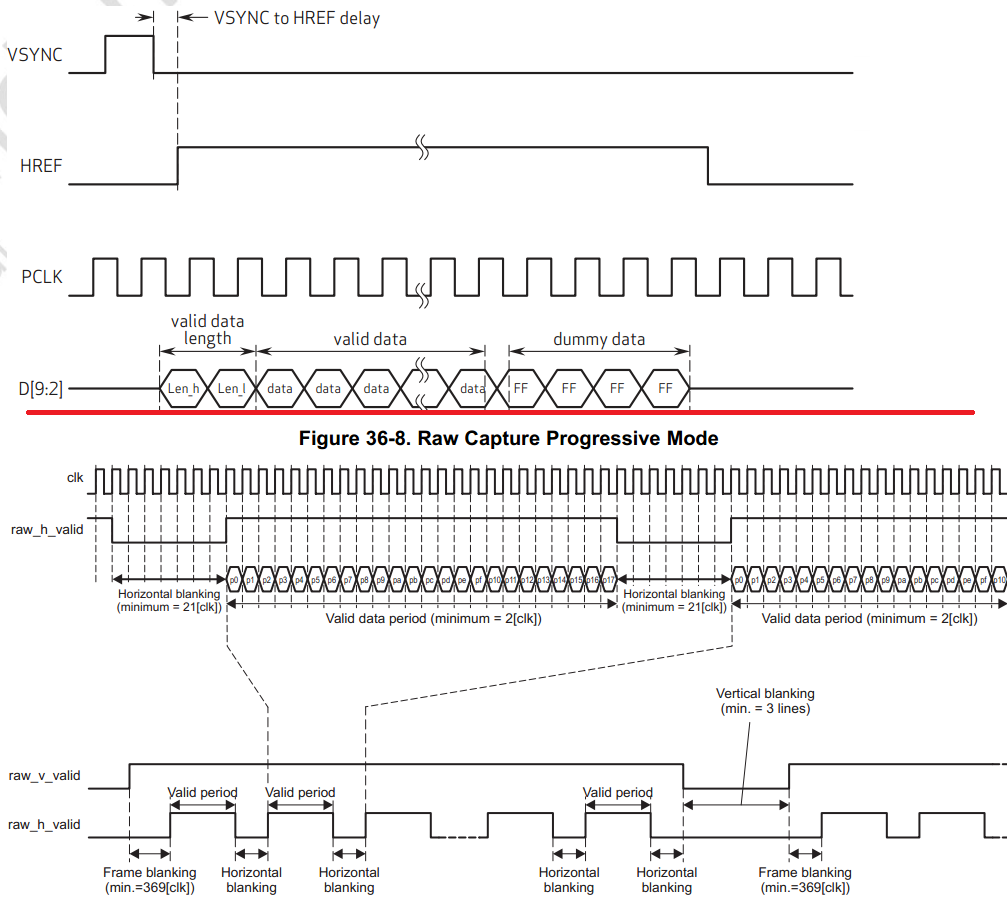
The signals outputted by Vsync and Href lines are in accordance with OMAPL13X VPIF document.
The PCLK signal (i.e. commonly fed to VP_CLKIN0 and VP_CLKIN1) are at 48Mhz
, while master clock fed into the image sensor from UI board of EVM board is 24Mhz
I'm trying to capture raw image data in progressive mode with 1280 * 720p format
Following are the register configuration used:
For Channel 0
Clkedge : Capture data on rising edge
Datawidth: 8 bits per pixel
INTLINE: 720p
FIDINV: 0
VVINV: 0
HVINV: 0
FIELDFRAME: FRAME
INTRPROG: PROGRESSIVE
VANC: 0
HVANC: 0
INTFRAME: TOP_ONLY
FID: TOP FIELD
YCMUX: 0
CAPMODE: CCD/CMOS RAW capture mode
CHANEN: 1
For Channel 1
Clkedge : Capture data on rising edge
INTRPROG: PROGRESSIVE
VANC: 0
HVANC: 0
INTFRAME: TOP_ONLY
FID: TOP FIELD
YCMUX: 0
CAPMODE: CCD/CMOS RAW capture mode
CHANEN: 1
Interrupt enable
INTEN: FRAME0 and FRAME1
Interrupt set register
INTSET: FRAME0 and FRAME1
Interrupt Enable Clear
INTENCLR: FRAME0 and FRAME1
Emulation Control Register
EMUCTRL: 0
DMA size control register
REQSIZE: 256
C0TLUMA: 0xC0000000
C0IMGOFFSET : 1280 * 720 * 2
The sequence followed is
- Disable VPIF Interrupts
- Disable Channel Enable
- Disable Horizontal and Vertical Ancillary Data
- Setup the above register values
- Enable interrupts for FRAME0 and FRAME1
- Enable clear interrupts for FRAME 0 and FRAME1
- Enable set interrupts for FRAME 0 and FRAME1
- Then setup interrupt service routine that gets called for both frame and line interrupt
Please have a look at the steps taken by me and kindly guide.
Also it would be more helpful if you can post your vpif settings.