This thread has been locked.

If you have a related question, please click the "Ask a related question" button in the top right corner. The newly created question will be automatically linked to this question.

Looking for DSP UBL in AIS file format for OMAP-L138

Other Parts Discussed in Thread: OMAP-L138, DA8XX, OMAP-L137, OMAPL138

When running  program “nand-writer_ccs33.out” on ARM of OMAP-L138,Console prints:

Starting DA8xx_NANDWriter.

DA850/OMAP-L138 part detected. Its a DSP  boot device

   You require three images to boot

   1) DSP UBL in AIS file format.

   2) ARM UBL in raw binary format.

   3) U-Boot image in raw binary format

To generate the AIS format file, you need to run the ARM/DSP .out (COFF) file generated from CCS build through the AISGen tool.

Enter the image type (one of "dspais" "armubl" "uboot" "other")


However, I only have armubl and uboot based on OMAP-L138 and cannot find out dspais for it. So I used an OMAP-L137’s dspais “ubl_C6747_NAND.bin”.But it failed.


Here’re my questions:1、Where can I get a dspais for OMAP-L138?

                                2、As I known,OMAP-L138 should be an ARM boot device but OMAP-L137 is a DSP boot device. Why is my OMAP-L138 a DSP boot device?        

                                Furthermore, I’ve noticed that the reason is my chip has no DSP RBL. Does this mean my chip is an incomplete one sold by accident?


  • Do you know the silicon revision, ROMID on the device.To find this information can you run this debug GEL file and provide us an dump.

    http://processors.wiki.ti.com/index.php/OMAP-L1x_Debug_Gel_Files

    Regards,

    Rahul


  • Thank you for your reply.I ran it before.And my silicon revision is 1.1.

    Regards,

    Cicy

  • Some earlier revisions of DA850 parts were DSP boot devices, if you provide us the entire dump of the GEL file we can look more into this and confirm your observation. In case you are looking for an DSP UBL that wakes up the ARM, you can use the DSP UBL from OMAPL137 to wake up the ARM and executes the ARM UBL.

    Regards,

    Rahul

  • Thanks a million for concerning about my post. Here’s the printout of debug gel:

    ARM9_0: GEL Output:  --------------------------------------------- 

    ARM9_0: GEL Output: |             Device Information            | 

    ARM9_0: GEL Output: --------------------------------------------- 

    ARM9_0: GEL Output: DEV_INFO_00 = 0x0B7D102F 

    ARM9_0: GEL Output: DEV_INFO_01 = 0x00000000 

    ARM9_0: GEL Output: DEV_INFO_02 = 0x0000001E 

    ARM9_0: GEL Output: DEV_INFO_03 = 0x00000000 

    ARM9_0: GEL Output: DEV_INFO_04 = 0x00000000 

    ARM9_0: GEL Output: DEV_INFO_05 = 0x00000000 

    ARM9_0: GEL Output: DEV_INFO_06 = 0x00000000 

    ARM9_0: GEL Output: DEV_INFO_07-DEV_INFO_08-DEV_INFO_09-DEV_INFO_10-DEV_INFO_11-DEV_INFO_12 = 0-0-0-0-0-0 

    ARM9_0: GEL Output: DEV_INFO_13,DEV_INFO_14,DEV_INFO_15,DEV_INFO_16 = 0,0,0,0 

    ARM9_0: GEL Output: ----- 

    ARM9_0: GEL Output: DEV_INFO_17 = 0x00030403 

    ARM9_0: GEL Output: DEV_INFO_18 = 0x00000000 

    ARM9_0: GEL Output: DEV_INFO_19 =

    ARM9_0: GEL Output: 0

    ARM9_0: GEL Output: 0

    ARM9_0: GEL Output: 1

    ARM9_0: GEL Output: 0

    ARM9_0: GEL Output: 0

    ARM9_0: GEL Output:  

    ARM9_0: GEL Output: ----- 

    ARM9_0: GEL Output: DEV_INFO_20 = 0x0001E000 

    ARM9_0: GEL Output: DEV_INFO_21 = 0x0001E000 

    ARM9_0: GEL Output: DEV_INFO_22 = 0x30303864 

    ARM9_0: GEL Output: DEV_INFO_23 = 0x3430306B 

    ARM9_0: GEL Output: ----- 

    ARM9_0: GEL Output: DEV_INFO_24 = 0x00000000 

    ARM9_0: GEL Output: DEV_INFO_25 = 0x00000000 

    ARM9_0: GEL Output: DEV_INFO_06 = 0x00000000 

    ARM9_0: GEL Output: DEV_INFO_26 = 0x00000000 

    ARM9_0: GEL Output:   

    ARM9_0: GEL Output: --------------------------------------------- 

    ARM9_0: GEL Output: |               BOOTROM Info                | 

    ARM9_0: GEL Output: --------------------------------------------- 

    ARM9_0: GEL Output: ROM ID: d800k004  

    ARM9_0: GEL Output: Silicon Revision 1.1 

    ARM9_0: GEL Output: Boot pins: 30 

    ARM9_0: GEL Output: Boot Mode: Emulation Debug 

    ARM9_0: GEL Output:  ROM Status Code: 0x00000086  Description:

    ARM9_0: GEL Output: Not supported for non-secure device 

    ARM9_0: GEL Output:  Program Counter (PC) = 0xFFFF0008 

    ARM9_0: GEL Output:  

    ARM9_0: GEL Output: --------------------------------------------- 

    ARM9_0: GEL Output: |              Clock Information             | 

    ARM9_0: GEL Output: --------------------------------------------- 

    ARM9_0: GEL Output:  

    ARM9_0: GEL Output: PLLs configured to utilize crystal. 

    ARM9_0: GEL Output: ASYNC3 = PLL0_SYSCLK2 

    ARM9_0: GEL Output:  

    ARM9_0: GEL Output: NOTE:  All clock frequencies in following PLL sections are based 

    ARM9_0: GEL Output: off OSCIN = 24 MHz.  If that value does not match your hardware 

    ARM9_0: GEL Output: you should change the #define in the top of the gel file, save it, 

    ARM9_0: GEL Output: and then reload. 

    ARM9_0: GEL Output:  

    ARM9_0: GEL Output: --------------------------------------------- 

    ARM9_0: GEL Output: |              PLL0 Information             | 

    ARM9_0: GEL Output: --------------------------------------------- 

    ARM9_0: GEL Output:  

    ARM9_0: GEL Output: PLL0_SYSCLK1 = 300 MHz 

    ARM9_0: GEL Output: PLL0_SYSCLK2 = 150 MHz 

    ARM9_0: GEL Output: PLL0_SYSCLK3 = 100 MHz 

    ARM9_0: GEL Output: PLL0_SYSCLK4 = 75 MHz 

    ARM9_0: GEL Output: PLL0_SYSCLK5 = 100 MHz 

    ARM9_0: GEL Output: PLL0_SYSCLK6 = 300 MHz 

    ARM9_0: GEL Output: PLL0_SYSCLK7 = 50 MHz 

    ARM9_0: GEL Output:  

    ARM9_0: GEL Output: --------------------------------------------- 

    ARM9_0: GEL Output: |              PLL1 Information             | 

    ARM9_0: GEL Output: --------------------------------------------- 

    ARM9_0: GEL Output:  

    ARM9_0: GEL Output: PLL1_SYSCLK1 = 300 MHz 

    ARM9_0: GEL Output: PLL1_SYSCLK2 = 150 MHz 

    ARM9_0: GEL Output: PLL1_SYSCLK3 = 100 MHz 

    ARM9_0: GEL Output:  

    ARM9_0: GEL Output: --------------------------------------------- 

    ARM9_0: GEL Output: |              PSC0 Information             | 

    ARM9_0: GEL Output: --------------------------------------------- 

    ARM9_0: GEL Output:  

    ARM9_0: GEL Output: State Decoder: 

    ARM9_0: GEL Output:  0 = SwRstDisable (reset asserted, clock off) 

    ARM9_0: GEL Output:  1 = SyncReset (reset assered, clock on) 

    ARM9_0: GEL Output:  2 = Disable (reset de-asserted, clock off) 

    ARM9_0: GEL Output:  3 = Enable (reset de-asserted, clock on) 

    ARM9_0: GEL Output: >3 = Transition in progress 

    ARM9_0: GEL Output:  

    ARM9_0: GEL Output: Module 0: EDMA3CC (0)        STATE = 3 

    ARM9_0: GEL Output: Module 1: EDMA3 TC0          STATE = 3 

    ARM9_0: GEL Output: Module 2: EDMA3 TC1          STATE = 3 

    ARM9_0: GEL Output: Module 3: EMIFA (BR7)        STATE = 3 

    ARM9_0: GEL Output: Module 4: SPI 0              STATE = 3 

    ARM9_0: GEL Output: Module 5: MMC/SD 0           STATE = 3 

    ARM9_0: GEL Output: Module 6: AINTC              STATE = 3 

    ARM9_0: GEL Output: Module 7: ARM RAM/ROM        STATE = 3 

    ARM9_0: GEL Output: Module 9: UART 0             STATE = 3 

    ARM9_0: GEL Output: Module 10: SCR 0 (BR0/1/2/8)  STATE = 3 

    ARM9_0: GEL Output: Module 11: SCR 1 (BR4)        STATE = 3 

    ARM9_0: GEL Output: Module 12: SCR 2 (BR3/5/6)    STATE = 3 

    ARM9_0: GEL Output: Module 13: PRUSS              STATE = 0 

    ARM9_0: GEL Output: Module 14: ARM                STATE = 3 

    ARM9_0: GEL Output: Module 15: DSP                STATE = 3 

    ARM9_0: GEL Output:  

    ARM9_0: GEL Output: --------------------------------------------- 

    ARM9_0: GEL Output: |              PSC1 Information             | 

    ARM9_0: GEL Output: --------------------------------------------- 

    ARM9_0: GEL Output:  

    ARM9_0: GEL Output: State Decoder: 

    ARM9_0: GEL Output:  0 = SwRstDisable (reset asserted, clock off) 

    ARM9_0: GEL Output:  1 = SyncReset (reset assered, clock on) 

    ARM9_0: GEL Output:  2 = Disable (reset de-asserted, clock off) 

    ARM9_0: GEL Output:  3 = Enable (reset de-asserted, clock on) 

    ARM9_0: GEL Output: >3 = Transition in progress 

    ARM9_0: GEL Output:  

    ARM9_0: GEL Output: Module 0: EDMA3CC (1)        STATE = 3 

    ARM9_0: GEL Output: Module 1: USB0 (2.0)         STATE = 3 

    ARM9_0: GEL Output: Module 2: USB1 (1.1)         STATE = 3 

    ARM9_0: GEL Output: Module 3: GPIO               STATE = 3 

    ARM9_0: GEL Output: Module 4: UHPI               STATE = 3 

    ARM9_0: GEL Output: Module 5: EMAC               STATE = 3 

    ARM9_0: GEL Output: Module 6: DDR2 and SCR F3    STATE = 3 

    ARM9_0: GEL Output: Module 7: MCASP0 + FIFO      STATE = 3 

    ARM9_0: GEL Output: Module 8: SATA               STATE = 3 

    ARM9_0: GEL Output: Module 9: VPIF               STATE = 3 

    ARM9_0: GEL Output: Module 10: SPI 1              STATE = 3 

    ARM9_0: GEL Output: Module 11: I2C 1              STATE = 3 

    ARM9_0: GEL Output: Module 12: UART 1             STATE = 3 

    ARM9_0: GEL Output: Module 13: UART 2             STATE = 3 

    ARM9_0: GEL Output: Module 14: MCBSP0 + FIFO      STATE = 3 

    ARM9_0: GEL Output: Module 15: MCBSP1 + FIFO      STATE = 3 

    ARM9_0: GEL Output: Module 16: LCDC               STATE = 3 

    ARM9_0: GEL Output: Module 17: eHRPWM (all)       STATE = 3 

    ARM9_0: GEL Output: Module 18: MMC/SD 1           STATE = 3 

    ARM9_0: GEL Output: Module 19: UPP                STATE = 3 

    ARM9_0: GEL Output: Module 20: eCAP (all)         STATE = 3 

    ARM9_0: GEL Output: Module 21: EDMA3 TC2          STATE = 3 

    ARM9_0: GEL Output: Module 24: SCR-F0 Br-F0       STATE = 3 

    ARM9_0: GEL Output: Module 25: SCR-F1 Br-F1       STATE = 3 

    ARM9_0: GEL Output: Module 26: SCR-F2 Br-F2       STATE = 3 

    ARM9_0: GEL Output: Module 27: SCR-F6 Br-F3       STATE = 3 

    ARM9_0: GEL Output: Module 28: SCR-F7 Br-F4       STATE = 3 

    ARM9_0: GEL Output: Module 29: SCR-F8 Br-F5       STATE = 3 

    ARM9_0: GEL Output: Module 30: Br-F7 (DDR Contr)  STATE = 3 

    ARM9_0: GEL Output: Module 31: L3 RAM, SCR-F4, Br-F6 STATE = 3 

    By the way, I’ve tried to use OMAPL137’s DSP UBL before. But it failed because of my ARM UBL is AIS file format. And I’m lack of ARM UBL in raw binary format. So could you provide one for me? Thanks a lot.

    Regards,

    Cicy

  • The ARM UBL source should be found under src/boot-strap/armubl-#.#.#.#.tar.gz in the PSP release.

    From the debug GEL file, there is something weird, we are observing in the device info. On a normal device, the device info shouldn`t turn out to be zero. Are you using a custom board or the evaluation module for your development? If this is a custom board are you applying power to the USB/SATA pins?

    Regards,

    Rahul

  • Thank you so much for your reply again. I've burnt these 3 boot files sucessfully. However,there's no printout in the HyperTerminal window after I changed my board into NAND Boot Mode.

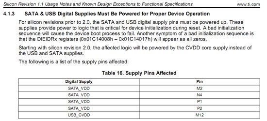
    This is a custom board designed by myself. And it has no USB port. So I didn't supply power for USB.But I do apply power to the SATA pins. Is this the key reason why my board couldn't work well?

    Regards,

    Cicy

  • Hi cicy,

    Did you fin out the problems with your based OMAPL138 custom board? Could you see any prompt in the Hyperterminal window like "Uboot>" or something like that. At the moment, I am at the same situation than you. I got flashed the SPI Flash (in my case) with the three OMAP bootloaders (dsp-ais-spi.bin, ubl-spi.bin and uboot.bin) correctly but then it did not work. Please, let me know if you fix your problem. Thanks in advance

    Regards

    Óscar

  • Oscar,

    What is the version of the PSP release you are using ? OMAPL138 is an ARM boot device so I am not sure why you are using a DSP UBL? could you specify the function of each of your boot binaries.

    Regards,

    Rahul

  • Hi Oscar,

    My problem has been solved by changing the version of my 138 chip into V2.0 because of I didn't supply power to its USB pins.And you could find out the reason in details in its <<silicon errata.pdf>> file as follows:


    Best Regards,

    Cicy O(∩_∩)O~