This thread has been locked.

If you have a related question, please click the "Ask a related question" button in the top right corner. The newly created question will be automatically linked to this question.

C6748: Interrupt latency

Other Parts Discussed in Thread: TMS320C6748


 Hi all,

 I am working on our custom design that contains a C6748 (@456MHz) and a Cyclone IV FPGA that is connected to the EMIFA. Via CS3 I can access several registers on the FPGA, via CS4 we can do USB-communication. I wrote a none-bios-application that polls our USB-communication in the main-loop, works nice.

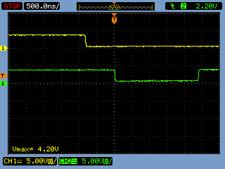
I have set up a timer that generates Interrupts with 10kHz. When the interrupt occurs, the DSP reads and writes some registers on the FPGA, that works too. But when I watched the different chip-selects by oscilloscope to determine the workload of the EMIFA, I saw a big latency in the execution of the timer-interrupt. I attached a screenshot of the oscilloscope. 

 You can see the polling of the USB-connection in blue, then the interrupt occurs, but there is about 1500ns stall where nothing happens on the EMIFA. Then there are the read/write-operations on the FPGA and another stall afterwards. I tried nearly everything I could imagine, but it doesn't change much (Debug<->Release, optimizations, inlining...).

The main-loop solely consists (after the initialisation) of a while(1) that polls the USB-connection via a HWREG(). In the interrupt I followed the starterware-examples to reset the flags (TimerIntDisable, IntEventClear, TimerIntStatusClear) and only do 2 operations on the EMIFA , also via HWREG(). By the way, the program is in L2RAM located.

Does anyone know the origin of that latency and/or how to remove it?

Thanks,

Chris


  • Chris

    What is the relationship between CS4 and USB? When you say USB connection in blue, are you saying USB is connected to a host and starting to send/receive data? CS is an active low signal, so the 1500ns you are seeing could be the read/write operation, not the stall.

    Thanks

    David

  • Hi David,

    Sorry for not explaining that. We have one FPGA connected to the EMIFA that gets the CS3 and CS4-signal. Among others the FPGA provides a custom USB-Connection which can be accessed via CS4. So in the first 1000ns of the screenshot the polling of our USB-connection can be seen, where the DSP (currently no DMA or so involved) checks if data, that came via USB, is present (in other words we check our fifo's "used words" in the FPGA if it is non-zero).

    Then the timer-event occurs that is mapped to INT4 of the DSP-core. There we have that stall of 1500ns before we can access the FPGA again (this time via CS3) to service our real-time-control in the interrupt-routine (for frequency converters and gear like that). I didn't try it yet, but it seems to me that I could get a better performance if I polled the interrupt-flag. But that seems so wrong to me... (at least for the real-time part)

    I'll try to describe a use-case, that should generate the issue seen on the screenshot (of course very abstracted, all hardware-initialization/data-transfer and so on omitted):


    #define TA 1e-4   //  10 kHz
    #define TIMER_PERIOD (unsigned int)(TA * 24e6)

    void tmr_isr();

    void main(void)
    {

     unsigned int usb_read = 0;

    dsp_init();   // our custom initialization (omitted here, PLL to 456MHz, EMIFA)

    /* 32bit - Timer0 1:2 */
     TimerConfigure(SOC_TMR_0_REGS, TMR_CFG_32BIT_UNCH_CLK_BOTH_INT); //Timer0: 2x32bit
    TimerPeriodSet(SOC_TMR_0_REGS, TMR_TIMER12, TIMER_PERIOD);
     TimerEnable(SOC_TMR_0_REGS, TMR_TIMER12, TMR_ENABLE_CONT);

    /* ------ Interrupts ------*/
    IntDSPINTCInit();
    IntGlobalEnable();

    /****** INT4 ******/
     IntRegister(C674X_MASK_INT4, tmr_isr); // INT 4: Timer
    IntEventMap(C674X_MASK_INT4, SYS_INT_T64P0_TINT12);
    IntEnable(C674X_MASK_INT4);
    TimerIntEnable(SOC_TMR_0_REGS, TMR_INT_TMR12_NON_CAPT_MODE); // Int Enable
     HWREG(SOC_TMR_0_REGS + TMR_INTCTLSTAT) |= TMR_INTCTLSTAT_PRDINTEN12;

    while(1)
    {
         while(usb_read == 0)
              usb_read  = HWREG(0x64000000);   // here we poll the USB-part of the FPGA (the first 1000ns that can be seen)

         // command-extraction/responding (coming here) omitted too
    }

    }

    void tmr_isr() 
    {

    unsigned int interrupt_read = 0;
    TimerIntDisable(SOC_TMR_0_REGS, TMR_INT_TMR12_NON_CAPT_MODE);
    IntEventClear(SYS_INT_T64P0_TINT12);
    TimerIntStatusClear(SOC_TMR_0_REGS, TMR_INT_TMR12_NON_CAPT_MODE);

    interrupt_read = HWREG(0x62000000);   // this is the 1500ns-delayed access to the FPGA via CS3

    // real-time-control also omitted

    TimerIntEnable(SOC_TMR_0_REGS, TMR_INT_TMR12_NON_CAPT_MODE);

    }

    Thanks,

    Chris


  • Chris

    The /CS is an active low signal, device is accessed when /CS is low, or are you putting an inverter externally to invert the /CS signal? You can take a look at the EMIFA asynchronous timing  on page 115, 116, and 117 of the datasheet: http://www.ti.com/lit/ds/symlink/tms320c6748.pdf.

    You can also configure EMIFA interface for asynchronous access by programming CEnCFG, AWCC register. For more detail, please talke a look at section 18.2.5 of C6748 TRM: http://www.ti.com/lit/ug/spruh79a/spruh79a.pdf.

    Besides /CS signal, can you also probe other EMIFA signals?

    Thanks

    David

  • David,

    i was involved with this project until some weeks ago.

    I would like to point out that this is not a EMIFA issue in my opinion. I am pretty sure having noticed this delay at interrupt entry without any relation to the memory interface. By the way, all the memories connected to the interface work fine, which are synchronous RAM as well as asynchronous access to flash memory and the FPGA mentioned by Chris.

    My approach was something like this:

    ---

    while(1) {
    // some other code here
    some_pin ^= 1;
    }
    timer_isr() {
    // int-related stuff here,  same as in Chris' post
    some_pin = 0;
    }

    ---

    Now, in case pin-toggling ist interrupted while pin is high, there is a delay until it is set low agin within the ISR.

    Question is, how long such interrupt entry delay is supposed to be. We did not find any numbers for reference regarding timing on interrupt entry and exit and typical ISR prologue processing.

    regards,

    Kai

  • Kai,

    From your scope screen shot, it looks like there is an extended memory access period to SDRAM via CS0 on timer interrupt. Do you have a similar screen shot with the GPIO pin toggling? We do not have numbers for interrupt latencies, but they are not very significant - more so that this is a non-BIOS application - so BIOS scheduling also does not come into the picture.

    Here are a few things you can try to increase performance:

    1) Use the max possible EMIFA frequency with optimal SDRAM timing configuration

    2) Turn on L1P/D and L2 cache (see below for general recommendations on cache configuration)

    3) Try increasing priority for DSP_CFG in the Master Priority 0 Register (MSTPRI0) from 2 to 1 or 0

    4) Use DDR2/mDDR on EMIFB for program code if possible

    Regards,

    Sunil Kamath

    General cache configuration:

    Code (.text) – DDR (or SDRAM)

    L1D/P – leave as 32K cache (and turn on cache)

    L2 – use 64K cache, the rest SRAM (for starters)

    Stack – L2 SRAM

    Heap (fast) – L2 SRAM (only if needed)

    Heap(slow) – DDR (or SDRAM)

    (SYS/BIOS lets you split the heaps)

  • Sunil,

    CS0 being low does not necessarily mean that there is any access, as this is the default selection when idle. I can not provide a screenshot for the toggling example, unfortunately. Cache usage and having a closer look at the SYSCFG priorities seem quite promising to me. Christian's task ;-)

    Regards,

    Kai

  • Sunil,

    I provoked the behaviour that Kai mentioned. See the screenshot below. I used a standard GPIO with the starterware-functions like GPIOPinWrite(). The main-loop only toggles the GPIO, the interrupt forces the GPIO low. The same delay-time of about 1500ns can be seen.

     I tried to implement your hints to increase performance, but it didn't help yet:

    1) EMIFA is configured to 100 MHz, SDRAM-timing-settings coincide with the datasheet (IS42S16160D).

    2) I tried CacheEnable(L1PCFG_L1PMODE_32K | L1DCFG_L1DMODE_32K | L2CFG_L2MODE_64K); from dspcache.h from the starterware. It shortened the delay by about 100ns, not as much as I hoped. Following the Reference-Manual of the TMS320C6748 (SPRUH79A) chapter 4.2 the default configuration of L1P and L1D already is cache. Does that mean that it is also used? Or do I have to tell the DSP over again to use it (you wrote "and turn on cache")?

    3) I set the DSP_CFG-priority to 0, SATA and UPP to 7 (we don't use them) and left the DMA at priority level 2. Sadly no change.

    4) We don't have DDR2-RAM on our board, all our applications fit into L2 SRAM. In my opinion this should bring a even better performance, because if the DSP can't fetch a instruction in L1P it is at the latest found in L2 and not further away. SPRUFK5A chapter 2.4.1 says: "On a program fetch, if the tag matches and the corresponding valid bit is set, then it is a "hit", and the data is read directly from the L1P cache location and returned to the CPU. Otherwise, it is a "miss" and the request is sent on to the L2 controller for the data to be fetched from its location in the system."


    Regards,

    Chris

  • Hello Sunil and Kai,

    I tried another setup to measure the latency between the occurance of an interrupt and its ISR. I simply configured an external GPIO as input- and interrupt-pin (falling-edge). At the beginning of the ISR, the DSP clears another GPIO to 0, does its control-task and rises the GPIO back to 1. Here the latency is no longer as long as it was before, just about 800 ns.

     Below is a screenshot that shows the timing. The yellow signal is the trigger, the green one is the "answer" in the ISR.

    Unfortunately, this improvement is quite useless to us, as we mainly operate through the EMIFA to get and set all the values (actuating variables etc.).

    Regards,

    Chris