This thread has been locked.

If you have a related question, please click the "Ask a related question" button in the top right corner. The newly created question will be automatically linked to this question.

What is the correct way to change the PWM duty cycle?

Other Parts Discussed in Thread: OMAP-L138

Looking for suggestions on changing the PWM consistently and glitchlessly.

I need to implement a dimmable LCD backlight on our design.  Using a simple configuration of the eHRPWM I'm able to initialize and run the PWM to control the backlight.  However, I'm not able to change the PWM's duty cycle in a consistent manner.

On start up the PWM is configured to generate a waveform with a 50% duty cycle.  The action qualifier is configured to toggle the PWM signal when the period counter (PRD) equals counter compare A (CMPA) or counter compare B (CMPB).  To change the duty cycle I make only change; write a new value to the counter compare A register.  Here's a simple diagram that shows how I expect this to work.


____________1                                   

                            |                                   

                            |_______________2 and 3 

1 - CMPA -- when period counter = CMPA toggle (expect signal to go high)

2 - CMPB -- when period counter = CMPB toggle (expect signal to go low)

3 - PRD count

I see two issues when changing the duty cycle

  • changing CMPA does not always change the duty cycle as expected. Most times increasing CMPA increases the on time (expected behaviour) but occasionally this will reduce the on time.
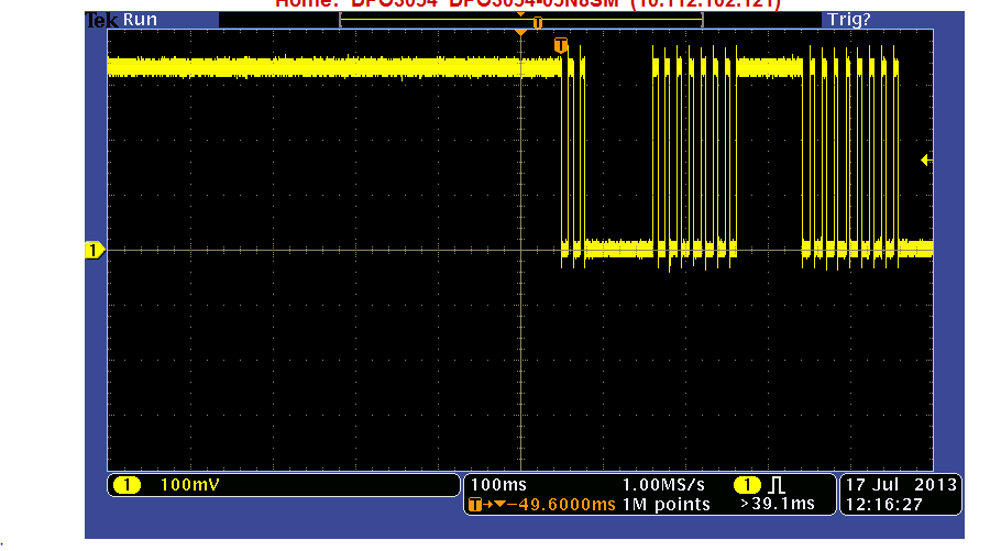
  • changing the duty cycle is glitchy.  For a short period of time the PWM output produces a signal at a constant level, before the updated PWM waveform appears.  This constant level is visibly noticeable on the LCD.
Enabling shadow register writes provides no improvement. 
Code to change the duty cycle is shown below.  I tried with shadow writes enabled and disabled.  With shadow write enabled I tried loading CMPA when the counter equals zero and the period.

void pwm_change_duty_cycle(uint32_t on_time)
{
    uint32_t on_period; 
    bool ret = 0;

    on_period = (pwm_period_counter * on_time)/100;

    /* Load Compare A value */

    //ret = EHRPWMLoadCMPA(SOC_EHRPWM_0_REGS, on_period, EHRPWM_SHADOW_WRITE_DISABLE,
    // EHRPWM_COMPA_NO_LOAD, EHRPWM_CMPCTL_OVERWR_SH_FL);

    ret = EHRPWMLoadCMPA(SOC_EHRPWM_0_REGS, on_period, EHRPWM_SHADOW_WRITE_ENABLE,
               EHRPWM_COMPA_LOAD_COUNT_EQUAL_PERIOD, EHRPWM_CMPCTL_OVERWR_SH_FL);

}

Code to initialize and start PWM is shown below:

uint32_t clock_div_val = 0x700;
uint32_t pwm_period_counter = 1820;

void pwm_start(uint32_t pwm_module_freq)
{

    /* TimeBase configuration */
    /* Configure the clock frequency */
    EHRPWMTimebaseClkConfig(SOC_EHRPWM_0_REGS, pwm_module_freq/clock_div_val, pwm_module_freq);

    /* Configure the period of the output waveform */
    EHRPWMPWMOpFreqSet(SOC_EHRPWM_0_REGS, pwm_module_freq/clock_div_val,
    (pwm_module_freq/clock_div_val)/pwm_period_counter, EHRPWM_COUNT_UP, EHRPWM_SHADOW_WRITE_DISABLE);

    /* Disable synchronization*/
    EHRPWMTimebaseSyncDisable(SOC_EHRPWM_0_REGS);

    /* Disable syncout*/
    EHRPWMSyncOutModeSet(SOC_EHRPWM_0_REGS, EHRPWM_SYNCOUT_DISABLE);

    /* Configure the emulation behaviour*/
    EHRPWMTBEmulationModeSet(SOC_EHRPWM_0_REGS, EHRPWM_STOP_AFTER_NEXT_TB_INCREMENT);

   /* Configure Counter compare sub-module */
   /* Load Compare A value */
   EHRPWMLoadCMPA(SOC_EHRPWM_0_REGS, (pwm_period_counter/2), EHRPWM_SHADOW_WRITE_DISABLE,
                     EHRPWM_COMPA_NO_LOAD, EHRPWM_CMPCTL_OVERWR_SH_FL);

    /* Load Compare B value */
   EHRPWMLoadCMPB(SOC_EHRPWM_0_REGS, pwm_period_counter, EHRPWM_SHADOW_WRITE_DISABLE,
                     EHRPWM_COMPB_NO_LOAD, EHRPWM_CMPCTL_OVERWR_SH_FL);

   /* Configure Action qualifier */
   /* Toggle when CTR = CMPA OR CMPB */
   EHRPWMConfigureAQActionOnA(SOC_EHRPWM_0_REGS, EHRPWM_AQCTLA_ZRO_DONOTHING, EHRPWM_AQCTLA_PRD_DONOTHING,
              EHRPWM_AQCTLA_CAU_EPWMXATOGGLE, EHRPWM_AQCTLA_CAD_DONOTHING, EHRPWM_AQCTLA_CBU_EPWMXATOGGLE,
              EHRPWM_AQCTLA_CBD_DONOTHING, EHRPWM_AQSFRC_ACTSFA_DONOTHING);

   /* Bypass dead band sub-module */
   EHRPWMDBOutput(SOC_EHRPWM_0_REGS, EHRPWM_DBCTL_OUT_MODE_BYPASS);

   /* Disable Chopper sub-module */
   EHRPWMChopperDisable(SOC_EHRPWM_0_REGS);

   /* Disable trip events */
   EHRPWMTZTripEventDisable(SOC_EHRPWM_0_REGS, EHRPWM_TZ_ONESHOT);
   EHRPWMTZTripEventDisable(SOC_EHRPWM_0_REGS, EHRPWM_TZ_CYCLEBYCYCLE);

   /* Event trigger */
   /* Generate interrupt every 3rd occurance of the event */
   EHRPWMETIntPrescale(SOC_EHRPWM_0_REGS, EHRPWM_ETPS_INTPRD_THIRDEVENT);
   /* Generate event when CTR = CMPB */
   EHRPWMETIntSourceSelect(SOC_EHRPWM_0_REGS, EHRPWM_ETSEL_INTSEL_TBCTREQUCMPBINC);
   /* Enable interrupt */
   EHRPWMETIntEnable(SOC_EHRPWM_0_REGS);

   /* Disable High resolution capability */
   EHRPWMHRDisable(SOC_EHRPWM_0_REGS);

}

  • Hi Dinesh,

    Thanks for the post.

    The duty cycle configuration shall be done at the end of each PRD.

    TI has provided the example program to change the PWM duty cycle.

    Please try or refer the example project provided in the wiki link below.

    http://processors.wiki.ti.com/index.php/C6747_EHRPWM_Example#Project_Purpose

  • Hi Rajasekaran,

    Thanks for the info and the link.  With this information I was able to solve one issue; I can now get the duty cycle to change in a consistent manner.  

    However, the glitches observed when making the change to the duty cycle still remain.  I probed the PWM output of the OMAP and I can see that every time I change the duty cycle there is a short period of time when the output is pulled high or low.  The image attached shows a scope capture of the PWM output. The periods where the signal is consistently high or low are points where I request a change in the duty cycle.

    I tried disabling the internal pull up resistor on the PWM signal and this had no effect on the behaviour.  It seems to that the PWM module relinquishes control of the signal at some point during the update.  Any suggestions on how to eliminate this glitch?

    If it helps here are the two changes I made

    When setting up the PWM use compare counter A only and specify actions explicitly instead of simply toggling

    /* Configure Action qualifier */

    /* When CTR = 0 go high when CTR = CMPA go low */
    EHRPWMConfigureAQActionOnA(SOC_EHRPWM_0_REGS, EHRPWM_AQCTLA_ZRO_DONOTHING, EHRPWM_AQCTLA_PRD_EPWMXAHIGH,
    EHRPWM_AQCTLA_CAU_EPWMXALOW, EHRPWM_AQCTLA_CAD_DONOTHING, EHRPWM_AQCTLA_CBU_DONOTHING,
    EHRPWM_AQCTLA_CBD_DONOTHING, EHRPWM_AQSFRC_ACTSFA_DONOTHING);

    Use shadow mode writes and update CMPA when period counter reaches PRD.

    ret = EHRPWMLoadCMPA(SOC_EHRPWM_0_REGS, on_period, EHRPWM_SHADOW_WRITE_ENABLE,
    EHRPWM_COMPA_LOAD_COUNT_EQUAL_PERIOD, EHRPWM_CMPCTL_OVERWR_SH_FL);

  • I looked into this a little more and it turns out that the default setting for the emulation mode bits in TBCTL is causing the glitches.  If I set these bits to Free Run mode (02h) then everything seems to be fine.  The problem seems to be fixed but some explanation about what's happening under the hood will help.

    Thanks.

  • Hi Dinesh,

    Thanks for the update. Please find my analysis on this.

    0 - It stops the PWM output when there is a change in TBPRD (That is next time base counter).

    1 - It stops the PWM output when counter completes a whole cycle on selected mode.

    2 - It never stops the PWM output.(Free run)

    FREE, SOFT:

    0h - Stop after the next time-base counter increment or decrement

    1h - Stop when counter completes a whole cycle:
    • Up-count mode: stop when the time-base counter = period (TBCNT = TBPRD)
    • Down-count mode: stop when the time-base counter = 0000 (TBCNT = 0000h)
    • Up-down-count mode: stop when the time-base counter = 0000 (TBCNT = 0000h)

    2h-3h Free run 

    Reference to EHRPWM Linux Driver:

    I have checked the LCD brightness control on OMAP-L138 linux using EHRPWM driver. The PWM should be enabled in Free run mode.

    If you would like refer ehrpwm Linux driver, Please download PSP release package DaVinci-PSP-SDK-03.22.00.02 from below link.

    http://processors.wiki.ti.com/index.php/DaVinci_(ARM9)_PSP_Releases#AM18x

    Refer the source file: DaVinci-PSP-SDK-03.22.00.02/src/kernel/linux-03.22.00.02/drivers/pwm/ehrpwm.c 

    Function: ehrpwm_pwm_start()