This thread has been locked.

If you have a related question, please click the "Ask a related question" button in the top right corner. The newly created question will be automatically linked to this question.

What is TIMINT in the register view of C5515 debug?

Guru 15580 points

CCSv5, using C5515 DSP.

Can someone explain the meaning of TIMINT in the register view of the C5515 debug?
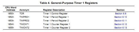
TIMER1	
TCR 0x8000 Memory Mapped Register: Timer Control
TIMPRD1 0x3A34 Memory Mapped Register: Timer period LSW
TIMPRD2 0x0000 Memory Mapped Register: Timer period MSW
TIMCNT1 0x0000 Memory Mapped Register: Timer Counter LSW
TIMCNT2 0x0000 Memory Mapped Register: Timer Counter MSW
TIMINT 0x0001 Memory Mapped Register: Timer interrupt

I cannot find this in the Timer User Guide (sprufo2). Here are the registers listed in the guide.

The other pertinent register is the timer interrupt aggregation register, which is located at 0x1c14h.

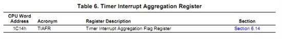
However, when I reset the Timer 1 interrupt bit in the TIAFR, the TIMINT bit does not get reset. 
What is the TIMINT bit and why does it appear in the register view of the C5515 debug screen?
  • Hi Mike,

    That TIMINT register (0x1816@IO) is a superfluous register that has been replaced by the TIAFR - 3 timers share one interrupt & this register decodes which timer fired the interrupt.

    We caught and deleted TIMINT from the documentation long ago, but we had not deleted it from the CCS4 register view yet.

    Thanks for bringing this to our attention. I have filed a bug against it. We will fix it in the next release.

    Regards,
    Mark

  • Mark,

    Thanks for the verification. 

    I suggest you have someone take a look a the rest of the CCS V5 register labels. There are others that do not match the current documentation (ie SPIDIR1, SPIDIR2, etc).

  • I'm slightly confused now. I see that only one interrupt fires regardless if timer 0, 1, or 2 causes it. Subsequently, there is one timer ISR that needs to check the TIAFR register to determine the source of the interrupt. I also see that there is an overall timer interrupt enable bit (4) in the IER0 register.

    My question is, if I only plan to use timer 0, how to I guarantee that the interrupt only fires as a result of the timer 0 counter expiring? What specifically enables interrupts individually? Is does simply writing a non-zero value in the respective timer counter register start the process and do the enabling?


    Thanks,
    Adam 

  • Hi Adam,

    See the general purpose timers CSL examples: c55xx_csl_3.00\ccs_v4.0_examples\gpt\CSL_GPT_NestedIntrNmiExample...

    Download CSL from www.ti.com/tool/sprc133

    Refer to C5515 System User's Guide: 1.6.3 Timer Interrupt Aggregation Flag Register (TIAFR) [1C14h]

    Each timer can be enabled/ disabled by the TIMEN bit of TCR register. When the timer is disabled, it does not generate interrupts.

    When the timer is enabled (TIMEN bit of TCR) and bit 4 (TINT) in IFR0 the timer interrupt aggregation flag register (TIAFR) latches each timer (Timer0, Timer1, and Timer2) interrupt signal when the timer counter expires. Using this register, the programmer can determine which Timer generated the single Timer CPU interrupt signal.

    Hope this helps,
    Mark

  • That's embarassing, I looked right past that field in the TCR description within the SPRUF02 timer user guide! Thanks for the quick reply.


    Adam