This thread has been locked.

If you have a related question, please click the "Ask a related question" button in the top right corner. The newly created question will be automatically linked to this question.

C6747EVM psp 01_30_00_06 audio example question about L2 cache

Other Parts Discussed in Thread: OMAP-L137

I can see at line 84 in audioSample_io.c a BUFALING definition for L2 cache so I assume that L2 cache will be used. However, Global Settings in audioSample.tcf shows the next dialog

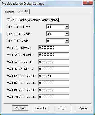
Cache settings is enabled but no memory size is assinged to L2CFG Mode, why? Moreover MAR 128-159 bits are setting to 0x0000ffff that signifies that 256MB of memory is cacheable beginning at address 0x80000000. My board  is an OMAP-L137 EVM so I believe this has not sense. I think MAR bits should be setting from 192-223 with a bitmask of 0x0000000F that match with my EVM board. Could anyone confirm this? I do not understand provided audio example configuration. Thanks in advance, gaston

  • Hi!

    I am also just starting to look at DSP/BIOS configuration system.  It turns out that .tcf can be edited as text file or via the GUI. Not all settings defined in text can be interpreted by the GUI.  So I am not sure how does the GUI parser make sense of the .tcf. Looking from object oriented perspective the GUI is a just a fancy interface to set and modify properties of the DSP/BIOS configuration objects which works only up to some point. I am trying to run these examples from CCS v4 and all the search paths and configurations have to be manually set.

    Regards!
    Atmapuri

  • Atmapuri said:
    Not all settings defined in text can be interpreted by the GUI.  So I am not sure how does the GUI parser make sense of the .tcf.

    Just out of curiosity, which configurations are you using in the .tcf script that the GCONF utility is not properly parsing? To my knowledge the GUI should be able to interpret all changes in the script as the two are completely compatible.

    With regards to the original question, I echo your confusion regarding the comment in the BUFALIGN definition. The .tcf file is placing all code sections in SDRAM, but it is placing all data sections in IRAM. To me this looks like L2 cache alignment is irrelevant with regards to an audio buffer; however, as the L1D line size is 64 bytes (if memory serves), this would help ensure that the buffers are aligned with the L1D memory as well.

    I hope this helps some, but maybe one of the folks more familiar with the design of these examples can chime in as well.

  • Adding to Tim's answer.

    Please see:

    http://tiexpressdsp.com/index.php/C6747_Audio_Example_cache_configuration

    Also, please not that whenver you use the GUI to add cache, it creates memory section at the end of IRAM for cache.

  • Hi!

    About changes in .tcf not showing in the GUI:

    bios.ECM.ENABLE = 1;

    It is related to ECM_dispatchPlug, but I dont know yet what either of that is doing.  Selecting any one child node in the GUI for Combined Event Manager causes the GUI to lock up. Other stuff not presentable in GUI looks like this:

    if (bios.MEM.STACKSIZE < 0x1000) {

        bios.MEM.STACKSIZE += 0x1000;
    }

    Thanks!
    Atmapuri