This thread has been locked.

If you have a related question, please click the "Ask a related question" button in the top right corner. The newly created question will be automatically linked to this question.

TXB0108 Problems converting

Other Parts Discussed in Thread: TXB0108, SN74LVC8T245

I am using a TXB0108 data converter. This is used with a PIC32 chip which is working at 3.3V and an image sensor (Hamamatsu S10077) working at 5V. I use one of the lines to transfer a clock signal whilst all other connected pins are driven low. When I provide a clock signal (1MHz) from the PIC to the converter, to be sent through to the sensor, the output at the converter is 2.6V max (not 5V as expected). Furthermore there is a lot of ringing on the clock signal seen at the output of the converter. I would like the converter to provide an output of a 5V clock signal running at 1MHz.

The TXB0108, VccA is connected to 3.3V with a 100nF decoupling capacitor. VccB is connected to 5V with a 100nF decoupling capacitor. The OE signal is connected pulled high to 3.3V using a 10k ohm resistor. The input/output from the PIC32 is connected to port A and port B is used to connect to the sensor. Unused ports are connected directly to ground.


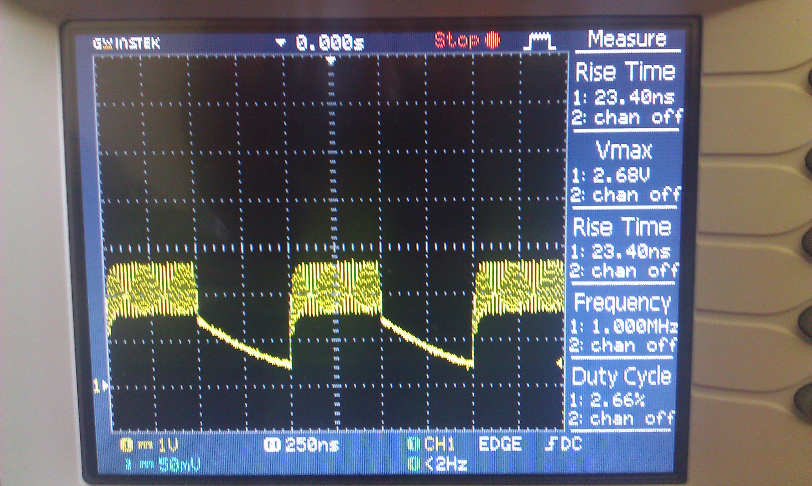
The image attached shows you the output at the PORT B IO pin where I am expecting the clock signal.


Am I connecting the translator correctly and can someone point me in the direction as to why this might be happening.

Thanks all.


  • It looks like you may have a capacitive load of over 70pF on the line. Is this possible? Are your traces long, or going to a connector, or the Hamamasu input very capacitive?

    The TXB devices are not recommended for use when the load is heavy. For these systems we recommend a direction controlled translator like the SN74LVC8T245.

    Another issue might be if you have pull-up or pull down resistors on the line.

  • Hi Hattie,


    Thank you for your response.


    I have looked at trying to calculate the capacitive load of the sensor. I have used the formula, P = C*V^2*f, and capacitive load value to be 2.8 nF. Hope this is the correct method.

    The IO lines are maybe a 2-3 inches long either side. Could this be enough to have such an effect?I do have a couple of headers as the voltage translator currently sits on its own PCB for ease of testing.

    I have not got any pull up/down resistors either on either side of the translator.


    If it is due to a capacitive load, could it still only go upto 2.5 V rather than 5V?


  • Capacitive loading can cause oscillation like that shown in your scope shot. It looks like it's oscillating around 2.5V 

    'One-shots' are edge acceleration circuitry. When there is loading, the low-to-high 'one-shots' may not reach the VCC before they time out. If the voltage they reach is low enough, it may be at a threshold that activates the high-to-low 'one-shots.' 


    Are these single direction signals? Can you use a device that does not auto-direction sense, but uses a direction control pin?

  • i have the same problem the TXB0108 add noise on the 5 volt any recomndion ?

  • I have completely the same problem. I try to make SPI communication between MSP430(3.3V) and a serial to GPIO converter (5V). And the result is the same output undulation like Meththa had attached...

  • I rip out the serial to GPIO converter (5V). Waveform on the output is the same. LCR meter shows that the capacitive load of the trace on the output is about 30-35pF (100Hz-100kHz). Any idea?