This thread has been locked.

If you have a related question, please click the "Ask a related question" button in the top right corner. The newly created question will be automatically linked to this question.

MAX232 overheat problem

Other Parts Discussed in Thread: MAX232, MAX202, MAX3232

Dear All,

Please don’t take this mail as a beginner mail. I have really a serious problem that turns my twelve months product design to a waste.

I designed a an RS232 interface board and used MAX232CWE+  16 wide SOIC

I used 1uF/50V SMD Case B Aluminum Electrolytic capacitors for MAX232. I use a generic 100nF SMD capacitor as a decoupler of MAX232.

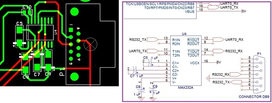
You can see my sch. and layout parts below;

Here is my problem,

When I connected my system to a PC serial port via an RS232 cable  (19200 baud and no parity, etc);

1.       There is no problem first. System is communicating correctly.

2.       I started to disconnect  and connect  the serial port periodically while my finger was on the MAX232 to measure the heating  J

3.       In some way MAX232 is starting to overheat and the serial line is starting to not working.

4.       If I close my system while MAX232 is heating, waits MAX232 get cold for nearly 1 minute and plug the system again there is no problem. MAX232 is working well.

5.       If I don’t close the system, MAX232 is damaged because of the heating.

6.       I dumped the problem with an oscilloscope. When I send some bytes to the system via a PC I should see nearly 12,13V if there is no problem but when the IC is damaged, I see only 1V at the R1IN pin (13. Pin) of MAX232. So I’m sure that MAX232 R1IN pin was collapsed  the PC transmit signal. Please note that none of five capacitors for MAX232 was not damaged or heating up.

7.       I changed the MAX232 IC and all of the rouitine is starting again. I did this nearly 10 times J

8.       Please also note that I double checked the capacitors polarity. There is no  problem for all

9.       In maxim site It tells about an ERRATA for MAX232CWE+( Product Change Notice 801-ERRATA) ; However I couldn’t find this document. I suspected that this IC has a BUG that I encountered

10.   I’ve searched the internet for 1 week and there are same problems but all of explanations are about look at the directions of the caps, etc.

11.   I found a forum thread on TI forums below and a person named David connected a 20 ohm series to MAX232 VCC and solved his problem. It is not a good but may be a reasonable solution

http://e2e.ti.com/support/interface/etc_interface/f/392/t/123614.aspx

12.   I know there is a TI employee could check my problem in detail. If you do I’ll be very glad

Waiting for your urgent reply

Ertan

  • Saltan,

    I have tried to get the MAX232 to overheat but I was not successful. Can you return a couple devices to your distributor as defective for failure analysis. It would be good to return samples that have the overheat issue but still work after cooling off. Also return some that are permanently damaged (don't work when cool).

    The C3 capacitor can be placed in either location for either device. It does not affect the charge pump action.

  • Hi,

    I've connected the C8 negative pin to VCC and measured the VCC, V+, V- for damaged and not damaged IC at run time. Please see below 
    NOT DAMAGED MAX232 ON BOARD 
    VCC: 5.09V 
    V+ : 9.3V 
    V- : -8.71V 
    Some Pins of MAX232: Squarewave signals 
    Heating: NO 
    DAMAGED MAX232 ON BOARD 
    VCC: 5.09V 
    V+ : 4.3V 
    V- : 1.2V 
    Some Pins of MAX232: NO Squarewave signals 
    Heating: LIKE HELL 

    I'm pretty sure that the VCC is stable

  • Dear All,

    Do you think that the below switching freqencies are normal   

    MAXIM MAX232CWE+  : nearly 600KHz at pin 3

    TI MAX232 : nearly 45KHz at pin 3

    I read to many things on the net about charge pump capacitors. In short;

    - if you use fast switching you need lower capacitance

    - if you need low switching you need higher capacitance

    From this point of view, capacitors suggestions for  "600KHz and 45 Khz" are same and 1uF. for both TI and MAXIM ICs ???

    Do you have any comments for switching frequencies and capacitor selection

  • Saltan,

    45kHz is too low. I do not have data on hand for the nominal frequency of the charge pump. I will check some samples this week.
    It takes a lot of current to pull the V- pin positive. There is a Schottky diode to ground on the V- pin.

    On devices that overheat but are not destroyed, is the V- pin also positive? It seems that the MAX232 is latching up.
    Other users who added a VCC resistor may have prevented latch up by limiting the (SCR) hold current so the latch is unsustainable.

    I do not know where the trigger for the latch originates, but the trigger is certainly external to the device.

    Have you considered upgrading to the MAX202? It is the same cost and is a drop in alternative to the MAX232. Both device have the same function, but the internal schematics are very different.

  • Dear Ron,

    Thanks for your answer. Please see below for my answers;

    45kHz is too low.

    I see nearly 45kHz with an oscilloscope. 

    I do not have data on hand for the nominal frequency of the charge pump. I will check some samples this week.

    It takes a lot of current to pull the V- pin positive. There is a Schottky diode to ground on the V- pin.

    On devices that overheat but are not destroyed, is the V- pin also positive?

    Yes V- pin also positive for both TI, or MAXIM ICs. I tried them on the same PCB.

    It seems that the MAX232 is latching up. 
    Other users who added a VCC resistor may have prevented latch up by limiting the (SCR) hold current so the latch is unsustainable.

    I do not know where the trigger for the latch originates, but the trigger is certainly external to the device.

    Have you considered upgrading to the MAX202? It is the same cost and is a drop in alternative to the MAX232. Both device have the same function, but the internal schematics are very different.

    I do not use MAX202 But I can. Pins are ok but footprints are a little different. I may use it.

  • Saltan,

    You are correct, the MAX232 does run near 45kHz. It is the MAX202 and entire MAX/TRS32xx series that runs over 100kHz.

    The V- should always be negative in operation. I tried forcing V- positive (up to 1Amp), but it ran normally once, I stopped the abuse.

    I have not been able to get any MAX232 to latch-up (overheat) in the several times I have tried. Please try the MAX202 and let me know the result.


  • Dear Ertan Bey,

    When you design the circuit you didn't consider ESD considerations.  am sure that the shield of DB9 its connected direct to GND or not connected. I always use 100 ohm serial,100nF to GND  for each pin from DB9 to IC. 1 uF capacitors use as multilayer ceramic low ESD type instead Tantalum. Less space, lower price better performance.

    When you do this please share the results with us.

    BTW - There in mounting hole on trace to Pin# 8 of DB9 I hope its not plated hole and you have short to GND

    Sevgiler,

    Haim Rodrik - CEO/CTO

    jTrack M2M Tellocation Systems LLC

  • Note: Between the DB9 shield to board's GND connect via Ferrite bead parallel 1000pF/2kV 0805 capacitor.

      if you need more assistance feel free to use rodrik5000

  • I have reached this forum in search for a solution for the same latch-up situation.

    In my case I think I have found the scenario that causes the latch-up - every time the analog side RS232 pins of the chip are connected to a powered serial port (e.g. connecting a board with the MAX232 to a running PC's serial port) without power applied to it's power pins (i.e. the board not powered), once I apply +5V to the chip it immediately enters the latch-up condition. I have narrowed this to the TxD input - because it's driven with a negative voltage (negative idle voltage on RS232 line), the combination of rising VCC and negative input on TxD causes in my opinion the latch-up condition. This seems like a bug of these chips related to the silicon implementation.

    Can TI tech support check this analysis and try t simulate it too?

  • I.T.,

    The TxD input is the R1IN or R2IN pin on the MAX232, correct?
    I can try this this week.


  •  If you don't use the second  port T2  , the pin 10  must be fixed with a pull up .   Not every component have the internal pull up .


  • Hi Ron, any luck simulating the scenario I described? It's been over a week...

  • I.T,

    I tried biasing the RS232 inputs one at a time and both at same time before applying VCC. I also tried floating TIN inputs. I tried slow and fast VCC ramps. However, I did not see an increase in supply current.

  • Hi Ron.

    I have the very same problem of overheating... The conections are checked and I´ve made the same conections that the datasheet...

    Is there any chance that if some of the signals entering in Din1 o Din2 rises before Vcc is macking some latching in the MAX3232 that I´m using, and then gets overheat?

    We have a complete reel with almost 2500 units... and I have tryed almost 20 of it....

    Is there same way solve this?

    Here I´ve got the lot written in the reel:

    LOT:5397198WCW.

    Maybe that helps a little...

    PLEASE, LET ME KNOW...

  • [Transmitter inputs float if left unconnected (there are no pull-up resistors), and may cause supply current increases.

    Connect unused inputs to GND for the best performance. ] [extract by datasheet of ISL3243  Intersil ]

    In the past I had the same problem with a driver Maxim  ( 232 ? or  202 i don't remember ) and verify that the driver with input float  self-oscillated producing heat ; It was difficult found the defect because , when put a scope , the defect missed  .  

    I suggest to put a pull up resistor to fix the level of the driver .

    Let me know

  • Hi Lorenzo.

    It was already done...

  • Thanks Ron. To what voltage did you bias the inputs? In my case they were biased to about -10V.

    Maybe the problems reported in this thread are related to a problematic batch of chips?

  • I.T.

    I tried +12V and -12V. It is likely that some samples will be more prone to self heating than others.

  • Hi Ron.

    Do you have an updated info about this issue?

    I need to solve this problem as soon as possible...

  • Mart  n,

    Despite my best effort, I am unable to replicate the issue. I suggest returning the part to your supplier and ask for a failure analysis.

  • Hi again Ron.

    I´ve made some test with our circuit, and I´m shure that it is everything following the datasheet.

    And that´s why I buy some MAX3232CSE+ from Maxim Integrated and with the exact same circuit, the module works everytime...

    I´m not shure about why there´s a problem with your MAX3232, but I´ve found the solution in other manufacturer... 

    Still need to find a solution, so I´m going to speak with my local TI seller to try to send you some pieces of the integrated circuit, and (if I can) also try to send you one of my modules...

    Can you contact me through my email?

    Regards!

  • We have used this device for years and early on found that if unused, PIN 10 -- a TTL/CMOS input pin -- needs a 10K resistor to ground.  Any unused RS232 level input can be left open.

    The schematic in this thread shows the pin as floating . . . CMOS inputs cannot be safely left in this state.  I am just stressing what Lorenzo has already stated.

  • Having looked at your schematic a little more carefully, your DB9 connector has the ground miswired:  standard ground connection is on pin 5 in a DB9 when used for RS232 (pin 7 is ground in a DB25).  Pin 7 in a DB9 usually carries RTS, so perhaps this is also giving you some issues when attached to a PC . . . unless you are using a non-standard cable.

  • Dear Saltan,

    I have very similar problem, but my chip is MAX3387 from Maxim.

    I found that if one of the receiver inputs is positive (+12V in my case) and the other one is negative

    (-12V) then immidiately after powering-up chip enters latch-up condition and burn.

    See also application note from Exar: www.exar.com/common/content/document.ashx?id=21271

    Regards,

    Nikolai.

  • I have the same problem, max 232 stop working and overheating.
    this occurs randomly when I connect ttl side. 

    I has pin 11 (T1IN) unconnected. 

  • Try to fix the pin 11 to 5 V for example by 100k pull up but perhaps there an other trouble .  If you are using  exactly the MAX232 IC the pull up is unnecessary because a pull up is built in .  

    Input thresholds are both TTL and CMOS compatible.The inputs of unused drivers can be left unconnected since 400k Ω input pullup resistors to VCC are built in (except for the MAX220).


  • Hello,

    Maybe my solution will work for you.

    I had the overheating problem using MAX3232EPE chip. (it says Maxim on the package, but I'm pretty sure it's a Chinese clone, as I bought them on Aliexpress for $0.15 each).

    The solution was to connect the V+ cap to the Vcc with the negative terminal and NOT to the ground. (TI datasheet suggested this as an alternative wiring, since V+ voltage is larger than Vcc)

    In my case the problem was that the chip latched up on startup and drew a steady of 217mA while heating itself. I could track this down to the charge in the capacitors - if the chip was connected with all capacitors charged, the latch-up didn't happen.

    The chip was overheating independently on whether inputs were grounded or not. It only stopped overheating when I removed the V+ cap (obviously, stopped working properly as well). I experimented further by changing the capacitor values - it was latching only every second time (not every time, as before) when I reduced the V+ capacitor value, and it stopped latching when I connected the cap to the Vcc terminal with its negative end instead of GND.

    Thanks,
    R.

  • Hello.

    I was experiencing similar problem with MAXIM MAX202 IC: very often it could latch up and start overheating after I applied power to my device.

    I could narrow down the conditions when it latched up. My device takes +5V power from external PSU. If I plug the PSU plug into the mains socket when the device's power supply jack is connected to the power supply, MAX202 works fine. However, If I switch on the power supply first and connect the +5V power supply jack to the device after that, the IC would almost always latch and start overheating.

    This gives a  hypothesis that the IC starts overheating if its power supply rises too fast. Indeed, I checked it with an oscilloscope and my PSU takes a few milliseconds to raise the output voltage to 5 Volts, but plugging in the power supply jack into a working PSU gives a rise time of a few tenth of microseconds.

    I tried adding a 20 Ohm resistor between the Vcc pin of MAX202 and putting 10 uF capacitor between GND and Vcc pins of MAX202 and it resolved the issue. However, adding a 20 Ohm resistor (as mentioned in the first post) without the 10uF capacitor did nothing except limiting the current when the IC latched again.

    I hope that this helps someone having same overheating problems with MAX232-like ICs.