This thread has been locked.

If you have a related question, please click the "Ask a related question" button in the top right corner. The newly created question will be automatically linked to this question.

Debug DP83848

Other Parts Discussed in Thread: DP83848C, TMS570LS3137, DP83848YB

Hi,

I have tried to debug the connection to DP83848 to no avail, and will definitely appreciate any input. 

here is my test with an oscilloscope:

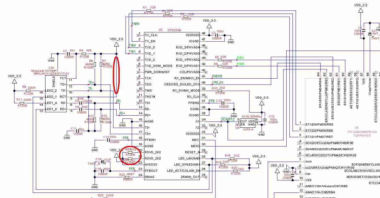
PWR_DOWN (pin 7) - 3.3v

RX_DV/MII_MODE (pin 39) pulled up to 3.3v --> configured as RMII mode

AVD33 (pin22), IOVDD33(pin32, 48) - 3.3v

X1 (pin 34) - 50 Mhz from osc

MDC (pin 31)  - 1.5Mhz

I wanted to try the simplest test, which is to read in the PHY_ID (register 02 and 03) but no reply is given back. I have probed the MDIO and MDC signal, the clock is good, and the MDIO shows the correct signal sent to PHY but there was no reply from PHY. I have sent to default phy address 00001h.

I checked the PHY address pins on DP83848, and something seems weird to me:

In the datasheet it was mentioned that the PHYAD[0] has weak internal pull-up resistor. In my board, the PHYAD[0] (pin 42) was left floating but probing this pin shows 0v instead of being pulled high. Is there any settings that can caused this? If the PHYAD[0] is indeed low (0v), then the phy address sent by the mcu is wrong. 

Some further questions:

1) Is the MDIO/MDC available in both MII and RMII mode to access the registers in DP83848?

2) What will be the simplest test to check if DP83848 is alive / communicating?

3) Also for curiosity, after DP83848 is powered up, and WITHOUT any software configuration, should any/both the LED light up if the RJ45 is connected to a computer and assuming the magnetics/MAG jack are working good?

  • James,

    MDIO/MDC is available in MII and RMII mode.  Your expectations are correct that you should be able to use MDIO/MDC to access the registers in RMII mode. 

    Your analysis and choice of probe points thus far is spot on.  Everything looks good based on what you have measured thus far.  I would next suggest probing PFBOUT (pin 23) and PFBIN1/PFBIN2 (pins 18 and 37).  These three pins should be connected together and should measure approximately 1.8V.  I would recommend measuring right at the pin to make sure that the voltages are seen by the part. 

    After power up, with no software interaction, default straps (other than those you have already identified), and no connection to the RJ-45, the device should be configured for Auto-Negotiation with no link and no activity.  In this configuration, the link and activity LEDs should not be lit, but the speed LED should be lit.  This is because the speed LED indicates 100Mbps functionality and in Auto-Negotiation mode, the 100Mbps receiver is active.

    Patrick

  • Thanks Patrick, your suggestion is perfect. There must be some mistake on my board that the PFBIN are not conencted to the PFBOUT!, I have now 1.8v on three of the PFB and I can read the registers from the PHY. 

    I have some further questions:

    My LED_SPEED is light up always. When I connect to a computer now, this is the output of the LED:

    the LED_LINK will light up, followed very quickly by a LED_ACT and very quickly both are off. This pattern  then repeat every 2 second. And my MAG JACK at my PC doesnt even light up. Is this the indication that the phy is advertising auto negotiation?

    my AN_EN, AN1, AN0 straping setup are all following the datasheet pg 19.

    I expect this behavior for startup, but this also happens even after software configuration, which seems weird to me. Here is what I have sent:

     write_PHY (PHY_REG_BMCR, 0x8000);

    read_PHY (PHY_REG_BMCR) gives 0x3100 -- okay for me

    /* Check if this is a DP83848C PHY. */

    id1 = read_PHY (PHY_REG_IDR1);

    id2 = read_PHY (PHY_REG_IDR2);

    phy_id = ((id1 << 16) | (id2 & 0xFFF0));

    phy_id gives 0x20005c90 -- correspond to phy id - good for me

    /* Use autonegotiation about the link speed. */
    write_PHY (PHY_REG_BMCR, PHY_AUTO_NEG);

    regv = read_PHY (PHY_REG_BMSR);

    first read in loop gives - 0x7849 - not good

    second read in loop gives 0x7869 - okay for me

      /* Check the link status. */
      for (tout = 0; tout < 0x100000; tout++) {
        regv = read_PHY (PHY_REG_STS);
        if (regv & 0x0001)
    	{   	
          /* Link is on. */
          break;
        }
      }
    For this one - few first reading gives 0x900 -- bad for me --> bit 0 = 0 means link status not good?
    but after a few read, it gives 0x4f15 , which will break the loop.  I was suspecting this only occurs when the LED LINK light is good (which for me, as mentioned above, only hapens one sec and it goes off and repeat the cycle). This status also means false carrier sense latch and other bits.
    
    
    Is this more of a hardware issue?  Can I assume once my MCU I/O are configured to Ethernet mode and RJ45 is connected between computer and the MAG JACK of my board, the LED_LINK should be light up on both my computer and for the PHY as well? Assuming the link is perfectly good. Also, will this happen without any software configuration (or if software config is needed, what registers needed to be set?).
    Thanks!


  • ----------- REPOST FOR THE WEIRD FORMATTING ON LAST PART OF PREVIOUS REPLY -----------

    Thanks Patrick, your suggestion is perfect. There must be some mistake on my board that the PFBIN are not conencted to the PFBOUT!, I have now 1.8v on three of the PFB and I can read the registers from the PHY.

    I have some further questions:

    My LED_SPEED is light up always. When I connect to a computer now, this is the output of the LED:

    the LED_LINK will light up, followed very quickly by a LED_ACT and very quickly both are off. This pattern then repeat every 2 second. And my MAG JACK at my PC doesnt even light up. Is this the indication that the phy is advertising auto negotiation?

    my AN_EN, AN1, AN0 straping setup are all following the datasheet pg 19.

    I expect this behavior for startup, but this also happens even after software configuration, which seems weird to me. Here is what I have sent:

    write_PHY (PHY_REG_BMCR, 0x8000);

    read_PHY (PHY_REG_BMCR) gives 0x3100 -- okay for me

    /* Check if this is a DP83848C PHY. */

    id1 = read_PHY (PHY_REG_IDR1);

    id2 = read_PHY (PHY_REG_IDR2);

    phy_id = ((id1 << 16) | (id2 & 0xFFF0));

    phy_id gives 0x20005c90 -- correspond to phy id - good for me

    /* Use autonegotiation about the link speed. */
    write_PHY (PHY_REG_BMCR, PHY_AUTO_NEG);

    regv = read_PHY (PHY_REG_BMSR);

    first read in loop gives - 0x7849 - not good

    second read in loop gives 0x7869 - okay for me

    /* Check the link status. */
    for (tout = 0; tout < 0x100000; tout++) {
    regv = read_PHY (PHY_REG_STS);
    if (regv & 0x0001)
    {
    /* Link is on. */
    break;
    }
    }
    For this one - few first reading gives 0x900 -- bad for me --> bit 0 = 0 means link status not good?
    but after a few read, it gives 0x4f15 , which will break the loop. I was suspecting this only occurs when the LED LINK light is good (which for me, as mentioned above, only hapens one sec and it goes off and repeat the cycle). This status also means false carrier sense latch and other bits.

    Is this more of a hardware issue? Can I assume once my MCU I/O are configured to Ethernet mode and RJ45 is connected between computer and the MAG JACK of my board, the LED_LINK should be light up on both my computer and for the PHY as well? Assuming the link is perfectly good. Also, will this happen without any software configuration (or if software config is needed, what registers needed to be set?).
    Thanks!

  • Some updates:

    I read on some of the relevant post, and I found this:

    http://e2e.ti.com/support/interface/industrial_interface/f/142/t/193572.aspx

    As mentioned by Aking Jin, I tried his approach of setting forced 10mbps, and the LED on my computer light up, and the link led stays good on my phy as well. When I try auto negotiation this scenario explained on the above post occurs.

    Patrick, can you verify this behaviour?

  • Hi, I have the same problem: PHY doesn't answer to any register read on RMII (I tried all the PHY addresses 0..31).

    Own design: DP83848 + Microchip PIC32 with internal MAC. 

    (Don't care red circles..)

    Checklist until now:  X1 50MHz,

    power 3.3V on AVDD33+2xIOVDD33, grounded 2xAGND+2xIOGND+DGND,

    RX_DV/MII_MODE 2K2 pulled up for RMII mode, COL/PHYAD0 floating,

    The PFBIN1/2/OUT are tied together, ohm-checked on pins, 10uF+3x100n's are

    okay, still there is 720mV on them instead of 1.8V you mentioned.

    I checked MDIO on scope: START (01), RD (10), PHY_ADDRESS (0..31 all tried),

    REG_ADDRESS (00000)...then MDIOline goes tristate and pulls up, no answer

    from 83848. Is there any hint what caused this?  Can PFB problem set back RMII reading?

  • The PFBOUT pin should provide a 1.8V output.  That 1.8V powers on-chip circuitry via the PFBIN1 and PFBIN2 pins.  If you are not seeing 1.8V on these pins, then that should be the primary focus of debug.  Until this 1.8V supply is operating correctly, the device will not operate correctly.

    Since you have confirmed the connections for the PFB pins, I would suggest that you examine the RBIAS resistor.  This resistor sets the primary internal bias for the device.  There are two measurements that I would recommend:

    1. With the board powered up, measure the voltage across the RBIAS resistor.  The voltage should measure approximately 1.2V.
    2. With the board powered down, measure the resistance of the RBIAS resistor.  The resistance should be 4.87 kOhm +/- 1%.

    Based on the results that you are seeing, I suspect that there may have been a stuff error on the RBIAS resistor.  Most likely, the value of the RBIAS resistor is too high.  Perhaps it is 487 kOhms instead of 4.87 kOhms or something along those lines?

    Patrick

  • Thanks, Patrick,

    sorry for the false alarm..it was a simple soldering problem. Don't know where exactly,

    but manual re-flowing made it work. Previously I measured PFB voltage by a hand DVM,

    I touched the heel of the pins by a pointed probe, and maybe this pressed the pin to the PCB.

    Strange, because I measured the fairly constant 720..730mV on each pins.   I see you know

    a lot about the 83848: what are the "reserved" pins (20,21), is it important to pull them up

    through a 2K2 ?

  • Glad to hear that your problem is resolved.  Based on the symptoms you reported, a stuff error or a soldering issue would have seemed to be the most likely cause.

    The reserved pins (20, 21) connect to circuitry that is not used in normal operational mode.  It is important to pull these pins up to the 3.3V supply via a resistor.  Like many of our strap pins, we recommend a 2.2 kOhm resistor, but the exact value is not critical.  A resistor in the range of 1 - 5 kOhms should be sufficient.

    Patrick

  • I have another problem: 83848 reports link down

    My own designed board is Microchip PIC32MX695F512H with internal MAC + DP83848 PHY, TCPIP Stack v5.42.02.
    I have problem: my board can't get a IP address from DHCP. I debugged into
    call chain StackTask() - DHCPTask() - MACIsLinked(), which returned "link down" status,
    so DHCP discovery packets was not emitted, and whole communication couldn't get started.
     
    After some investigation:)) I see that link status is set at
    StackTask() - MACGetHeader() - EthPhyGetLinkStatus() - _PhyReadReg(PHY_REG_BMSTAT, _PhyAdd);
    which reads PHY's BMSR status reg through MDIO/MDC to check PHY's internal LINK_STAT bit.

    Status reg reading seems to be okay (eg. AN_ABLE reads1,  AN_COMPLETE=1,  all 4 BASE10/100 FD/HD bits are1's, etc.)
    but LINK_STAT bit reads 0 (I have a single PHY in the system, its adress is 1, Phy detect and Init functions are successful) 
     
    The strange part is that that at the same time DP83848 PHY's LINK LED "lives":
    lights up when RJ45 plugged in, and blacks out when plug removed (even if PIC32 prog not running).
    If I unplug the other end of cable from 10/100 switch, LINK LED normally goes off, so link detect bursts go through --magnetics seems to be fine.
     
    The 83848's BMSR register bit2 LINK_STAT even reads 0.
    Can Link LED and link status bit work separately?  MDIO+MDC are surely well connected, but

    there may be soldering errors at TXD0/1 RXD0/1 pins. Can they cause such a link problem despite the well-working link LED?

    Is there any hint what is the problem?

  • Hi,

    I have moved your post to the Ethernet forum.  To help with better supporting and tracking your future questions in Ethernet, please post any new Ethernet related questions into this forum.

    Thanks!

    Patrick

  • Hi, I'm trying to debug a DP83848YB, driven by a TMS570LS3137, and have the same problem of no response on the MDIO.

    I can see that the MDIO keeps cycling around the 32 PHY addresses but does not get a response: the PHY should be defaulting to address1 as the COL pin is open-circuit. By using a 10kohm pull-down as well as the 1.5k pull-up on the MDIO line, periods of tri-state can be identified. The MDC is set to 2.5MHz, but I've halved it with no change. The device is intended to run MII so has a 25MHz clock oscillator to pin1.

    I have the correct voltages as detailed by your first post.

    Although I only have a link LED (actually driven by an inverting FET from LED_LINK), it correctly goes out if the Ethernet port is linked to a laptop: it appears to be running at 100MHz.

    The TMS does not show any linked PHYs in the ALIVE register.

    Any suggestions please?

    Thanks

  • Hello,

    Can you open a new thread in the E2E form and share the schematics for your design? This thread is marked as "Answered" so opening a new thread with a link to this thread will help with tracking.

    -Regards,
    Aniruddha
  • After scrutinising the datasheet, I see that for a cold boot, I must wait for 167ms minimum before first clocking the MDIO. A long time! Of course with the Hercules development board, code is only loaded once the board is powered so the soft reset only needs odd microseconds to work.

    PHY now works, thanks
  • Hi King,

    The reason why it takes so long is because the PHY has bootstraps and also the PHY needs to wait for not only the supplies to stabilize but also the PLL.

    To be sure that the PHY is capable of sending and receiving error free data, this delay is needed.

    Best,
    Ross
  • Hi Patrick,

                I have seen this post of yours in the forum

                Exactly the same condition am facing with my board but the only difference is am getting 1.75 volt in PFB out instead of 1.8

                I cant able to read the physical register through MDIO/MDC pins .

                What are the things i have to do to ensure the chip is working 

               I am using STM32F407 MC  with mikro - e compiler  


  • Hi Ramasubbu,

    Please create a new thread with as much description of the issue as possible.
    This thread is closed.

    Thank you,
    Ross