This thread has been locked.

If you have a related question, please click the "Ask a related question" button in the top right corner. The newly created question will be automatically linked to this question.

Need a solution for driving an LVDS TFT LCD panel using an HDMI output from an embedded CPU board.

Other Parts Discussed in Thread: SN75LVDS83B, SN75LVDS83C, TFP401A

I am new to this forum and have browsed somewhat through it on this subject, but have not found a solution that helps me, so I thought I'd post.  I am an analytical chemist working on a project to design a handheld instrument which contains an embedded CPU board and an LCD panel.  The LCD panel we selected for the application has an LVDS interface (24-pins, some of which are for the LED back light).  The embedded CPU board we have chosen does not have a native LVDS output (I can get one with the addition of a bulky expansion board), but it does have an HDMI output. 

The supplier of the panel provided me with a large (8.5" x 3") board that uses a chip (RTD2662, from RMC) that is used to provide a wide range of video connectors (HDMI, DVI, SVideo) for inputs and it drives the particular panel we have been testing via a custom cable the integrator provided.  We were able to drive the panel as a second monitor via the HDMI output of a PC.  Thus, I know it can be done.

However, we are very space limited in our design, and this board is much too large for us, and is overkill.  I only need one HDMI input and the ouptut to go to the LVDS input of the panel.  I am looking for help to understand what this will take. 

Ideally, given our short development cycle, I would like to find a very small COTS circuit that would do this for me.  If that does not exist, then suggestions for the fastest route to a solution. 

Any help would be appreciated.

  • Hi Scott, welcome to our Engineer to Engineer community.

    Does your panel have a 1-channel or 2-channel LVDS input? (in other words, are there 3-4 data pairs or 6-8 data pairs?)  Also, what is the resolution?

    This application note describes a 2-chip solution to convert DVI/HDMI TMDS signals into 1-channel LVDS, which is can directly drive panels that have a 1-channel LVDS receiver:  http://www.ti.com/lit/pdf/slla325

    Thanks,
    RE

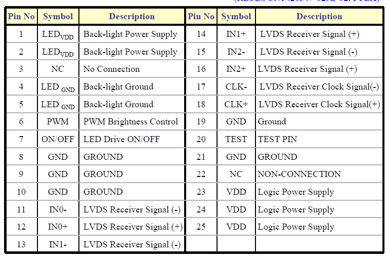
  • I am not sure about the 1-channel or 2-channel question.  The LVDS cable coming off of the display looks like it has 24 pins wired out of it, but the data sheet says there are a total of 25.  I'll try to past the pinout here.  The display is a 5.6" wide screen, with pixel resolution of 1280x800, and 18-bit color (6-bits per color channel).  What am I looking for to answer your question?  The conversion on this demo board appears to be focused on one chip, an RMC RTD2662.  There are other sizeable chips on the board, but this appears to be the main one.

    Scott


  • Thanks for providing that.  So there are 3 data pairs, and 1-channel LVDS.  In that case, the app note I linked should work for you.  At 1280x800, you will likely use a pixel clock frequency around 70MHz.

    Thanks,
    RE

  • Found it.  I guess I should actually read the 'entire' data sheeet, and not just the specs I'm interested in.  It say 1-Channel LVDS Interface. 

    Sorry, I'm an analytical chemist, not an EE (but I should still read the full data sheet)

  • Thanks for the quick answer.

    I am curious how you came up with the frequency, how critical it is, and how you 'adjust' or set it.

  • You're a jack of many trades!

    You will also want to look at your panel's expected bit order on the 3 serial data lanes.  That affects how you connect up the RGB inputs to the SN75LVDS83B (you can also use our new lower power device, the SN75LVDS83C).  Since your panel uses 18-bit color, you won't connect the two least significant color bits from the DVI receiver output (Red0, Red1, Blue0, Blue1, Green0, Green1).  And you will only use 3 of the 4 available LVDS data output pairs from the SN75LVDS83B/C.

    Best regards,
    RE

  • Your panel datasheet should list the acceptable clock frequency (or period) range.   ~70MHz (~14ns period) is a common frequency for 1280x800 resolution.

  • I found that section.  It states 71.1 MHz. 

    I have two follow on questions.

    1)   The embedded CPU we have selected does have an LVDS option, but it is part of a daughter board, which adds bulk to oiur system, and they are having driver issues.  As a backup, we were looking at the HDMI to LVDS approach, since the HDMI on our CPU is working fine.  My technical lead has stated to me on multiple occasions that LVDS is not 'really' standard, and that there are multiple chip sets for LVDS.  He told me that, as I searched for the right LCD panel for our design, I had to ensure that the chip used in the LVDS of the display was the mate of the chip used on our CPU.  Otherwise, it would not work, since they come as a 'set'. 

    How true is this statement?

    2)  Is there a COTS board that has already implemented the circuit design in the app report you pointed out to me?  We are in a time crunch (who isn't), so I am being asked to locate COTS solutions as much as possible.

    Thanks again for all the help. If we decide to go this route and are unable to find a COTS solution, is there a contact at TI with whom I could have our technology lead correspond to get answers to any questions he may have?

    Enjoy your weekend, everyone!


  • Scott,

    1) LVDS for Flat Panels is a "standard" that was originally developed for driving the video interface in Notebook PCs through the hinge.  As such it has been adopted by and utilized by multiple processor and panel (TCON) manufacturers.     TI's brand name for this is FlatLink™.  National (now part of TI) refers to it as FPD-Link.  These are interoperable with each other.  There are other suppliers of TX & RX who all meet the same standard interface.  There are newer higher resolution planels that support dual-LVDS which requires 8 differentail paris instead of the standard 4.  National also has whatthey call FPD-Link II and III which embed the closk and utilize a single differential pair.  These two require both the TX and RX as I am not aware of any panels that suppport this natively.

    2) Not sure what a COTS board is?  We may have an evaluation module depending on which device you are considering.

  • Thanks Dan.

    Scott, sorry for the delay in responding; I've been traveling internationally for 2 weeks.

    1) As Dan indicated, LVDS has been largely standardized by the industry.  It follows TIA/EIA-644-A voltages, and the standard is to use 7-bits per clock per lane.  You can generally match up any TIA/EIA-644-A transmitter with 7-bits per clock with any TIA/EIA-644-A receiver with 7-bits per clock.  Panels that have integrated LVDS receivers follow this.

    The panel's expectation of the serial bit order of the 27 bits can vary.  Most use "Format 1".  Any order can be accommodated by the connections between the GPU and LVDS transmitter.  See this: http://i40.tinypic.com/2hh39k8.png

    2) I'm also not sure what you mean by "COTS".  Maybe you want a board connection example?  This picture from our EVM guide shows connections: http://i43.tinypic.com/35lvr75.png  And here is our Flatlink layout guide: http://focus.ti.com/lit/an/slla012a/slla012a.pdf

    I'll be the contact for your technology lead.  You can email me at "reisenbeis <at> ti <dotcom>".

    Thanks,
    RE

  • COTS means Commercial Off The Shelf.

    http://en.wikipedia.org/wiki/Commercial_off-the-shelf

  • Hi RE,

    Need a quick clarification on your comment above.

    So, the 2 LSBs from the DVI (or HDMI) receiver output won't be connected because I have a 6-bit (instead of an 8-bit) panel. So, essentially, I will treat R2, B2 and G2 as my LSBs from the receiver output

    Does that mean, R2/B2/G2 outputs from the receiver gets connected to R0/B0/G0 on the LVDS transmitter inputs? Or, R2/B2/G2 outputs from receiver needs to be connected to R2/B2/G2 on LVDS transmitter inputs as well?

    I am basically trying to convert HDMI data to LVDS for a 6-bit panel.

    Thanks,

    Taif Syed

  • Taif, you would want to connect R2/G2/B2 from the DVI side to R0/G0/B0 on the LVDS side, and DVI R7/G7/B7 to LVDS R5/G5/B5.

    Best regards,
    RE

  • Hello RE,

    Thanks for the prompt response. So, just to confirm, bit[2] of HDMI receiver output becomes the bit[0] of the LVDS transmitter input, correct?

    Thanks,

    Taif Syed

  • That should be correct, assuming the lower numbered bits are the LSBs.

    Best regards,
    RE

  • I have a similar requirement to Scott's. Initially I'd like to use a 15.6" 1366x768 laptop panel which are now easily available. I think they are 1-channel LVDS input.

    The solution recommended was made in 2011. Is it still the best solution?

    What if I also wanted to drive a 1920x1080 laptop panel?

    I think 1920x108 requires  2-channel LVDS input.

    Scott: I'd be interested to know what solution you went for?


    CE.

  • Hello RE,

    I am using TFP401A as the HDMI Rx and SN75LVDS83C as the LVDS Tx, but my panel is a 6-bit panel. 

    My question is, do I discard (meaning leave unconnected) the QE[0:1] which is B[0:1] outputs from the HDMI Rx and treat QE[2], which is B[2], as the B[0] input on the SN75LVDS83C? 

    Or, do I just use QE[0:5] outputs from HDMI Rx as B[0:5] inputs on SN75LVDS83C and discard QE[6:7]. 

    So, the question is, do I discard 2 LSBs or MSBs from the TFP401A output for a 6-bit panel? Please confirm.

    Thanks

  • Taif, you'll want to discard the LSBs.

    Best regards,
    RE