This thread has been locked.

If you have a related question, please click the "Ask a related question" button in the top right corner. The newly created question will be automatically linked to this question.

about CAN transceiver SN65HVD230D

Other Parts Discussed in Thread: LM317, SN65HVD230, SN6501

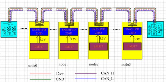
the datasheet of SN65HVD230D shows the device will not Disturb the Bus if it is Unpowered. But I find if one node is only connected by power+, GND is not connected. the whole CAN bus will not work normally. can anybody help me analisys the phynomenon ? the block diagram is showed below. input power is 12v, LM317 regurates the 12v to 3.3v for SN65HVD230D.


  • Unpowered on the datasheet refers to Vcc not connected, not to GND not connected. I guess that if you connect only Vcc, the device will find a (bad) way to close its power loop through the GND of another device on the bus, thus ruining the communications as you saw. You should search a way of disconnecting devices from the bus by disabling their power and not their ground. This can be done with another regulator instead of the LM317 (one with enable pin), or even better, a DC/DC with enable pin. If you want to stick to the 317, you can add a PNP based series transistor with the 317 to cut off the voltage.

  • Albert, thanks for your answer.

    Actually, my power is 24v  input,  lm317 regurates 24v  to 15v, then another dc/dc LT3470A  step down 15v to 3.3v. in order to simply the process,  so I say 12v power is regurated  to 3.3v by lm317. LT3470A  has /SHDN input pin. I connect it to 15v power+ input. the phenomenon still exists.

    I am not clear about this sentence" you can add a PNP based series transistor with the 317 to cut off the voltage."  Could you show me simply circuit?

  • I'm no expert on the LT3470A, but if the pin is labeled /SHDN as you say, then you will probably have to tie it to GND to enable shutdown mode, rather than +15V. 

    Are you simply trying to disable the SN65HVD230 from driving the bus? ? If so, pin 8 (Rs) can be used to put the device into 'listen only' mode. In this mode, it will still monitor the bus and report the signal on the R pin, but it won't transmit anything onto the bus. This is done by applying applying a voltage >0.75*Vcc to pin 8. 

    Let me know if you have any further questions!

    Jason 

  • please can you measure the voltage on CANH when the ground connection is lost? could you provide a scope shot too?

    I could imagine that CANH is consistently high and thus blocking the bus.

    regards, Thomas

  • When you disconnect GND on one CAN node this is called "loss of GND".  If the 24V is still connected at some point to the circuits the CAN node at this point will then be referenced to 24V not GND.  I would suspect at that point the system will then pull the common mode point of the CAN network up to the 24V and thus take it out of the operating CM range of the CAN devices.    If you are trying to disconnect power as many of the other threads have mentioned, you need to find a way to keep GND on and turn of the regulator.  There are also many voltage regulators on the market with an EN or INH pin that controls it's output. 

    -- Scott

  • jason, thanks for your reply.

    I  want  LT3470A to work normal, so I tie /SHDN to +15v. if it is tied to GND it will shut down.

    what  I want is that the CAN bus works well when the Groud of one node is lost due to uncertain reason. As the datasheet shows, pin 8 (Rs) is used to regurate the slew rate of output.

    linjie pan

  • dear,Thomas

    your imagine is right. When one node's GND is lost, CANH and CANL are consistently high(near to power + 24v) and thus blocking the bus, when the node is not pull out from the whole CAN bus.  But the whole CAN bus including CANH and CANL will be down to near groud when the bad node is tied to CAN bus.

    The phynomenon will happen in the feild application, So I advice the CAN transceiver should not disturb the bus even when one node's groud is lost

    best regards.

    linjie pan

  • dear, Scott

    your analysis is very correct. Of course, I will keep GND on, but in the Field application, the GND will loss due to some reason.

    As you say , I should change the regulator, I doubt the regulator with EN or INH pin will not solve the problem. yet  the regulator with /EN or /INH pin may be ok .

    best regards

    linjie pan

  • Hello Linjie,

    The Rs pin actually has several functions. If it is tied to GND directly, it will put the device into high-speed mode. As previously stated, pulling pin 8 to Vcc will put the device into listen-only mode, where it won't transmit. Slope control, as you mention, is the third option for this pin. This is done by pulling pin 8 to GND through a resistor, where the current is proportional to the desired slope. This is all explained on pages 20-22 of the datasheet.

    Now, none of that will help your actual problem of losing GND to the whole node. It sounds like one way to deal with this is to use an isolated power supply, so that the CAN transceiver won't see +24V in the event of loss of ground. The isolated supply should block the voltage from going through, leaving the CAN transceiver unpowered and not disturbing the bus.

    -Jason

  • You could then switch and use the ISO1050DW isolated CAN trasnceiver along with the SN6501 transformer driver plus a small LDO (making an isolated power supply) and create a CAN power domain with it's own GND reference which is fully isolated from your 24V and other GND reference.  Thus if you float 1 CAN node's CAN GND then it will be still referenced to the bus and not 24V.  This is is a significalty more complicated solution but it then eliminates all sort of GND issues as the CAN system has it's own GND and is not subject to ground shifts or losses.

    -- Scott