This thread has been locked.

If you have a related question, please click the "Ask a related question" button in the top right corner. The newly created question will be automatically linked to this question.

MSP430F5438A Security fuse blown

Other Parts Discussed in Thread: MSP430F5438A, MSP430F5419A, CC430F5137, MAX3232, CC430F6137, MSP430FR4133

Hi, we are developing a range of systems that use the MSP430, and are having issues with an error message about the security fuse being blown during debugging.

We are developing using Code Composer Studio v5.1.0.09000, using the MSP430F5438A (rev D and E), and the MSP-FET430UIF JTAG debugger. Our hardware is both Ti development boards (the MSP-TS430PZ5x100), and our own bespoke hardware using the BGA type package MSP devices.
So far, our work has been exclusively with the JTAG interface, and using CCS to launch debug sessions on the MSP devices. We are using the default debugger and linker settings, such that the application code and data are written to flash memory before debugging starts.

We are encountering a recurring problem whereby occasionally, an MSP430 will appear to end up with a blown 'security fuse'. So far this has happened 4 times, three times with development boards, and once with our own hardware. The 'fuse blowing' occurs exclusively at the launch of a new Debug session on an MSP430 in CCS. The debug session fails to start and either the "security fuse blown" or some other error is displayed. From then on, all debug access attempts result in the "security fuse blown" message, even when tried on other FETs/CCS installations.

We have not at any point set or accessed the security fuse features in the MSP430 from either CCS or our application code (the erase protected memory and enable BSL area read/write debug options in CCS are disabled). The problem has occured to several of our developers, each using different FET devices and CCS installs (all the same software version).

Once an MSP430 begins reporting a blown security fuse, it doesn't appear to run any code when powered up, and any previous software on the device is not running. In the case of development boards, we can replace the MSP430 chip in the ZIF socket, which returns the hardware to full working order. On our own hardware however, replacement is very difficult.

I have read in several places on the forum about accessing the BSL in order to regain access the MSP430 and then upload some code that can restore the security fuse setting to normal. This is somthing I would be interested to look into and gives hope for our 'bricked' hardware. However I am most interested in prevention over cure, and really want to understand what is happening to cause these issues in the first place.

I hoping someone out there can help me with the following questions:

  1. Are there any known situations where CCS and the FET programmer can cause an MSP430's Security fuse to become blown unintentionally? Is there anything we can do to avoid such issues?
  2. Are there known conditions where the Flash memory content could be damaged during debugging, resulting in corruption of the BSL or JATG Key that would result in these symptoms? Is there anything we can do to avoid them?
  3. Has anyone got any other ideas about what is going on?

Many thanks in advance for any help anyone can give.

Terry.

  • I am interested in this too, as we have an EVM that we tried to connect to with SBW.  The error message was also Security Fuse Blown.  I was under the impression that it was very difficult to turn this feature on and yet some how it was on and now we have a bricked board.

    Please advise.

    Brandy

  • The error 'security fuse blown' usually means 'a JTAG device seems to be there but does not respond'. Which of course is the purpose of a blown security fuese. However, in most cases this has a completely different reason:

    Typically the debugger tells the FET to reset the device. Once this is done, the debugger tells the FET to attach to the device and identify it. However, the time between the two commands can be relatively large (USB and its several layers of drivers, HUBs etc. introduce a large latency, compare dwith a direct parallel port output liek the original FETs had).
    It may happen that while the FET tries to attach to the MSP, the MSP resets. Which causes the JTAG interface to be reset too and the FET cannto attach. It then thinks the fuse is blown. But it is the applciaiton software that causes an endless reset circle, e.g. because of a password violation when the first instruction tries to disable the watchdog the wrong way. Voltage supervisor or such may cause similar effects. Or external reset controller/watchdogs.

    In case of a software-caused reset that prevents the JTAG from attaching, there are two possible solutions:

    1) add a monoflop to the RST line that stretches the length of the reset signal, so teh MSp remains in reset state longer, so it hasn't reached the faulty applicaiton code when the JTAG tries to attach.

    2) use the BSL feature to do a mass erase.

    It's not easy to accidentally blow the JTAG fuse on the 54xxA, unless oyu mess with the BSL. Because teh JTAG fuse is located in the BSL segement, which is normally protected.

    Even on the old 1x family devices, I often got a 'cannto access device - security fuse blown?' message (using msp430-jtag from the mspgcc toolchain), and on these devices, the fuse was a physical fuse which couldn't be blown under any circumstances with my cheap parallel port FET, even intentionally.

  • Hello Jens-Michael,

    Thank you for your thoughts.  This is my first experience with the MSP430 and I have to program it so that my c6678 evm will work.  If you have time, can you give me more information about using the BSL features to do a mass erase?  What will this do and does CCSv5 support this?  Do I need a different tool?  If the problem is a race condition between the JTAG and the reset line, wouldn't it happen more inconsistently?  For me, it seems even after several power cycles, the JTAG cannot connect.

    Thanks so much for your help!

    Brandy

  • There are several threads abotu the BSL.

    Basically, it is a serial (UART) connection independently of the JTAG system (and attached to different pins, usually TA0.0 and TA0.1 for TX and RX, in addition to RST and TEST). It starts a factory-supplied bootloader code that is executed before the user program and interprets several commands, including a mass erase program and password protection.. On the PC side, the tool 'BSL scripter' is used. Links and usage hints are on those other threads.

  • Thank you, I will look into it more on the forums.

  • Thanks Jens-Michael for your help with this. It is much appreciated and we've had progress.

    Yesterday I set up a system to access the BSL, and executed the BSL 'Mass erase' command on our 3 dev board MSP430F5438A devices that were reporting the 'security fuse' error. After this process the devices became responsive to JTAG debugging again and now work normally. Document SLAU319A was very useful in getting the details to do this. I've yet to attempt the process on our bespoke hardware but expect we will have the same result.

    This confirms what you were saying. It does seem that the security fuse has not been set, despite the misleading error message to that effect. Perhaps Ti might consider altering the wording of this message in a future CCS version to avoid future confusion..?

    My main question now is what happened to cause this situation in the first place. I understand what you said about the things the application software can do wrong that would cause these symptoms to occur, but I'm pretty sure this is not the situation in our case. We have had the problems occur when debugging known-working config controlled source code, which has been debugged successfully many times before and after the issue occurs.

    Are there any FET/CCS related issues (i.e. bad debug settings) that could result in failed debug sessions which leave the MSP430 in a badly programmed state, resulting in these symptoms?

  • Other than code that resets the MSP imemdiately, a possible second cause is the voltage supervisor. On soem MSPs, this could be misconfigured to even compare an external pin voltage and reset the MSP if it falls below a cwertain threshold. The problem is that the reset state won't be removed until the voltage rises above the threshold. The device doesn't simply reset and restart, but remain in reset until the voltage fits. It can cause the same symptoms and has the same solution (mass erase) besides aplying the expected voltage.

    Other than that I wonder how an existing and already workign software suddenly turns that bad. But apparently it was the software, as a mass erase revived the chips.

  • Hi Jens-Michael,

    Have you seen this same behavior with another software program (like the Elprotronic) ?  I am wondering if the extra delay could be coming from the CCS tool ?

    Has this been an issue wiht previous versions of CCS?

    thanks for your insight,

    Steve S

  • I suspect that our software doesn't even make it as far as the MSP430's flash when the problems occur.

    Typically what happens is that a chip will be running a program correctly from flash or the previous debug session. We start a new debug session, which will load new code into flash as part of the debug process. This debug process fails with some error, not always the security fuse - perhaps unknown device or some memory access error. From this point the MSP430 will be in the broken state. Any further debug attempts result in the 'Unknown device/Security fuse' errors until the device is mass erased via the BSL.

    We have the debugger set to halt at the first instruction upon starting a debug session. If it were our code causing the problem, I would expect to see the debugger hit the breakpoint at the first instruction first, and then the problem occur either when the execution of code started, or when the device power cycled such that it boots from the new program in flash.

    We don't get that far however, the debug session fails to start and the problems begin immediately. It is like something is causing the debug session to fail to start, and something that happens during that failed session is leaving the MSP430 in a bad state.

  • Steve Sager said:
    Have you seen this same behavior with another software program (like the Elprotronic) ?  I am wondering if the extra delay could be coming from the CCS tool ?

    You mean the delay between releasing reset and establishing the JTAG connection?

    I never used CCS. But I had similar problems with msp430-jtag (form mspgcc) and a parallel port FET. However, a JTAG lockup caused by bad code didn't happen for me for years now. Not since I finished my basic application frame code (own startup code instead of the default compiler startup code, and basic system initialization).
    However, with msp430-jtag i encountered frequent connection problems whcih vanished on a few retries. With the Elprotronic software I do not remember any. But then, I didn't use it too often for the projects that can be handled with the parallel JTAG. since msp430-jtag does nto need user interaction, it fits nicely into my makefiles.
    The main use for the Elprotronic software is with the USB JTAG and the 54xx devices, which cannot be handled by msp430-jtag at all due to the new JTAG comand set (20 bit addressing)

  • Hi Terence

    Even we faced a same problem in our company, but we use the sample version of mcu XMS430F5438, we found that if very large buffer loop is initialized before main, then this will create problem as WDT  will respond. Are you defining a huge buffer loop in your code?

    Best Regards

  • Harshith Ramesh said:

    Hi Terence

    Even we faced a same problem in our company, but we use the sample version of mcu XMS430F5438, we found that if very large buffer loop is initialized before main, then this will create problem as WDT  will respond. Are you defining a huge buffer loop in your code?

    Best Regards

    Hi Harshith, thanks for your suggestion, I can see how that would be a problem. However I don't think our issue is related to the behaviour of the code we are writing to the MSP430. We don't initialise any large memory spaces in our applications. If the issues were caused by something like that, I would expect them to occur consistently every time that code was run on the MSP430. In our case, the problem occurs intermittently and infrequently when a debug session is started. The same code that is debugged when we have problems will be debugged lots and lots of times with no issues at all.

  • Hi All,

    Since few days I also have this strange issue with security fuse blown with a MSP430F5419A.

    I updated CCS to v5.2 recently and works on W7 64bits.

    I occurs when I'm debugging and really don't know why, when, how.

    I tried with several boards (own board) and always have the same issue.

    I tried to erase all memory with Elprotronic, it works for one board but not for others.

    After some days I tried again other boards and then all where erased.

    But now my breadboard is "blown" again !!

    Is there a reliable solution, is it coming from W7, FET drivers, board hardware, CCS ??

    Regards

    Stephane

  • Dear Jens-Michael,

    I have the same problem and would like to try solution "1) Add a monoflop to the RST line". Is it sufficient to add a delay with a RC-filter (maybe followed by a schmitt-trigger)? That would delay both the negative and positive edge of the RST signal. If that is not sufficient (i.e. only the positive edge should be delayed), could you give me a link to the recommended implementation of the monoflop? Thanks in advance!

    Has anyone implemented the monoflop successfully?

    Regards

    Kalle

  • If your JTAG tool does not send a RST signal, then add a monoflop to the RST line does nothing.

    Instead, add a manual push-button to the RST line, push and hold it down until shortly after you started the JTAG tool would be more helpful. In some cases, you need to push down the RST before you apply Vcc, and release it shortly after you start the JTAG tool.

    The purpose is to prevent the target from executing any code already in its Flash after it is powered-up and before the JTAG interface is activated.

  • Kalle Ohlsson said:
    Is it sufficient to add a delay with a RC-filter (maybe followed by a schmitt-trigger)? That would delay both the negative and positive edge of the RST signal

    In many cases, the problem is that between releasign RST and starting the JTAG connection, there is a delay long enough to start the MSP and execute part of the faulty code. And crash.

    The monoflop is meant to delay the release of RST so much that the FET is ready to establish JTAG connection while RST hasn't been released too long ago.
    If the begin of the reset is also delayed, this doesn't make a difference. However, you might need some approaches to find the proper delay (use a pot for R to allow adjustments).
    You might still want to use a monoflop instead of a schmitt trigger because a simple R/C will not only delay the low edge, it will also swallow the reset completely if the pulse is too short (doesn't reach the threshold). A cheap dual retriggerable monoflop is the 74HC4538. You'll still need R/C for the time constant, of course.

  • Thanks, I'll order a 74HC4538 and test that solution.

    //Kalle

  • Thanks for that insight - even after using the BSL to do a mass erase I was having a problem with the blown fuse issue until I used the RST when starting the JTAG. Now I can load & debug code on the target again.

    I don't know exactly what is/was going on in my particular case, so "the cure" may work while obscuring a problem arising from some other cause, but I appear to be back in gear now.

    Thanks again.

    TB

  • Is it possible to mass erase of cc430f5137 uC using ttl232r ( http://www.ftdichip.com/Support/Documents/DataSheets/Cables/DS_TTL-232R_PCB.pdf )?

    If it is how can it be done?

    Regrets,

    Mihajlo

  • Mihajlo Bozovic said:
    Is it possible to mass erase of cc430f5137 uC using ttl232r

    No. As far as I can see, this device, as nice as it is, only has RTS/CTS but not DTR/DSR. However, both RS232 output signals (RTS and DTR) are required to put the MSP into BSL mode.

    You can use the 3.3V version of this device for UART transmissions between PC and MSP. Which is great and saves you the need of a MAX3232.
    But unfortunately not for BSL. Except if DTR is available at the chip pins and just not put on the header. You'd have to read the detail datasheet to figure this out.

  • I did the same thing manual reset.

    turn on CCS then run debug mode, I can see the Jtag trying to 7.8ms reset pulse. then the pop up blown fuse appeared. take manual reset the mcu then click retry..everything is downloading again.

    I see there might be something got to do with the reset pulse that too sensitive or no long enough could be one of the problems. But there definitely some else. which I am not sure what. And this thing happened quite frequent. Like once a week. I don't see problem on other manufacturer's mcu.

  • Hello all,

    I was in teh same "blown fuse" boat until I figured out something that is an alternative to the BSL method to erase flash when the USB FET doesn't "catch" the funky code in time to control a JTAG session.

    Like others, I tried:

    • Retrying a debug a bunch of times in CCS to gain control
    • changing the USB port, eliminating USB hub, etc.
    • Restarting CCS/computer
    • Using FETPro (lite)
    • Manually trying to hold reset line down to find a sweet spot when the FET could gain/maintain control

    Sadly, nothing worked and since I didn't have the BSL loader hardware (and wasn't prepared to make one) I STFW for hours to no avail.  Until it hit me: why can't I use the FETs SBW2 capabilities to access the BSL!  I just needed lower level control of the USB FET to do this... Enter the MSP430Flasher Tool.  

    Ultimately, I didn't use the BSL features of the USB FET but based on the following procedure, I was able to access the JTAG faster than CCS or FETPro-Lite:

    1. Download + install MSP430Flasher Tool
    2. In CCS or IAR, set the build options to output a TI .txt file to the ../Debug directory (this file format is required by the flasher utility)
    3. Write a dummy program to replace your funky code that's latching up the 430 and compile it
      1. i.e.
        #include <msp430.h>
        int main(void)
        {
          WDTCTL = WDTPW + WDTHOLD;                 // Stop watchdog timer
          while (1)
          {
            LPM4;
          }
        }
    4. Navigate to the ../Debug folder of the dummy project and copy the "<filename>.txt" file to the folder where MSP430Flasher is installed:
      1. typically this is: C:\ti\MSP430Flasher_1.2.1
    5. In a command window navigate to the directory where MSPFlasher is installed
    6. Enter the command to load the program
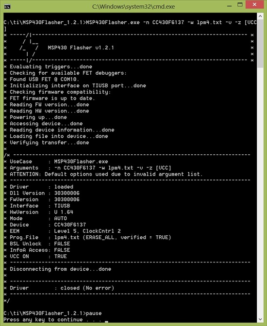
      1. "MSP430Flasher.exe -n CC430F6137 -w lpm4.txt -v -z [VCC]"
      2. NOTE: change the target from "CC430F6137" to your specific IC
      3. NOTE: it may prompt you to update teh FETs firmware - go for it unless you want to synchronize the MSP430.dll files between CCS and the command line flasher

    After this command is executed, you should see something like:

    (Don't worry about the "inavlid arguments list" error.)

    Based on my understanding of Michael Jens-Gross' numerous posts on this issue, the 430 flasher command line tool might be just a bit faster than CCS or FETPro programmers thus giving it the needed advantage to gain control of the micro after a reset.  (Hats off Michael - you're the man)

    Finally, if you're a sucky programmer (like me) and doing a lot of debugging/erasing, you're bound to screw it up again so do what I did: make this a batch file! :-)

    I hope this has helped a few people make this issue a little less daunting a task to rectify. Go MSP!

    Thank you,

    MK

  • Thanks for the alternative, MK - it's good to have options, particularly so when I'm shifting to board that don't have a reset button.

    I appreciate the time and effort that went into this...both the development & testing of the method and  the posting of the explanation & instructions.

    Best wishes,

    Tim

  • Thankyou, you saved my day!

    This solution worked for me. I wrote also my own batchfile and its working ;-)

  • Thanks for the good write-up and pointing out the MSP430Flasher utility.
    In my situation I was able to get everything working fine again but instead I had to use the utility to do an erase like this:
    MSP430Flasher.exe -n MSP430FR4133 -e ERASE_USER_CODE

    This may only apply to FR4xx devices.
    Thanks again!

**Attention** This is a public forum