• Join
  • Sign In with my.TI Login
Texas Instruments
  • Products
  • Applications
  • Tools & Software
  • Support & Community
  • Sample & Buy
  • About TI
Sample & Purchase Cart Sample & Purchase Cart
  • Search
  • Advanced
TI E2E™ Community
  • Support Forums
  • Blogs
  • Groups
  • Videos
  • 简体中文
  • More ...
TI Home » TI E2E Community » Support Forums » Microcontrollers » MSP430™ Microcontrollers » MSP430 Ultra-Low Power 16-bit Microcontroller Forum » Do we need pull ups in SPI with SD card
Share
MSP430™ Microcontrollers
  • Forum
  • Announcements
  • E2E Wiki
Options
  • Subscribe via RSS
MSP430 Resources
  • MSP430 Product Folder
  • MSP-EXP430G2 - MSP430 LaunchPad Value Line Development kit
  • MSP430 Getting Started Guide
  • MSP430 Microcontroller Projects
  • More Resources >
  • Do we need pull ups in SPI with SD card

    Do we need pull ups in SPI with SD card

    This question is not answered
    Aamir Ali
    Posted by Aamir Ali
    on Sep 21 2012 06:56 AM
    Expert2115 points

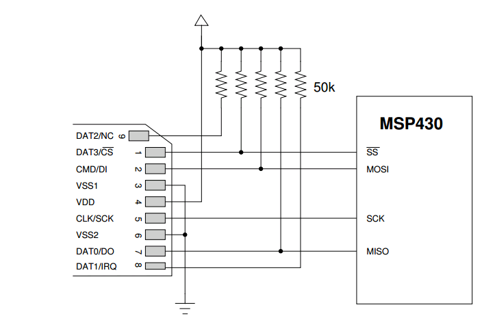
    1. I was reading MSP430 interface with SD card & found the schematic below. Do we need pull up on MOSI & MIS0 lines. Won't they slow down the speed ot they are optional.

    2. Is it necessary to pull up 9 pin & gnd 8 pin

    3. I am working on 4GB class 4 SD card. Is the entire range is writable or some is protected.

    If I chose 512 bytes sector, then no of blocks are = 4GB/512 bytes. Is it??????? 


    MSP430 sd card
    Report Abuse
    • Reply
    You have posted to a forum that requires a moderator to approve posts before they are publicly available.
    All Replies
    • seb
      Posted by seb
      on Sep 21 2012 07:42 AM
      Expert2390 points

      I am using SPI with a FLASH device and I am not using any PullUps. I think SPI never needs those pullups, because is it able to set and reset the lines internally.

      Perhaps they switched it up with the I2C, because I2C needs those pullups on the signal lines, because it cannot provide a High logic itself.

      Anyway if you are not sure and have the space available on your PCB I would plan them in , since you still can leave them unpopulated if not needed.

      Report Abuse
      • Reply
      You have posted to a forum that requires a moderator to approve posts before they are publicly available.
    • Jens-Michael Gross
      Posted by Jens-Michael Gross
      on Sep 21 2012 09:37 AM
      Guru140435 points

      The pullups make sure that SD card won't get erroneously into a wrong state when the MSP isn't ready and all its pins (especially SCK and SS) are high-impedance inputs. But personally, I never had pullups and did not discover any problems.

      having the pads and leave them unpopulated until needed is surely a good advice.

      However, I use a small resistor (33 Ohms) in series to VCC, to limit the inrush current when the card is inserted (I had it sometimes resetting my processor, and a resistor is cheaper than an additional larger capacitor for stabilizing)

      _____________________________________
      Before posting bug reports or ask for help, do at least quick scan over this article. It applies to any kind of problem reporting. On any forum. And/or look here.
      If you cannot discuss your problem in the public, feel free to start a private conversation: click on my name and then 'start conversation'. But please do so only if you really cannot do it in a public thread, as I usually read all threads. And I prefer to answer where others can profit from it (or contribute to it) too.

      Report Abuse
      • Reply
      You have posted to a forum that requires a moderator to approve posts before they are publicly available.
    • Peter Bigot
      Posted by Peter Bigot
      on Sep 21 2012 11:21 AM
      Expert1380 points

      The EXP430F5529 User Experience code, which interfaces to an SD card on the board, configures the internal resistor to pull-up on MISO (SOMI for TI folks).   I found a rationale for this at http://www.avrfreaks.net/index.php?name=PNphpBB2&file=viewtopic&t=113786.  In this case it might be important since there are other peripherals on the same bus.

      What I remain unconvinced of is whether the internal resistor works when the pin is configured to its peripheral function, and more so when it's configured for peripheral but the peripheral is in SWRST.  At any rate, I haven't proven that doing it causes problems, though I'm still trying to track down a PMMKEY reset when I write data to the card.  (I did increase VCORE, though from the schematics and its ineffectiveness I'm not convinced it's relevant.)

      Report Abuse
      • Reply
      You have posted to a forum that requires a moderator to approve posts before they are publicly available.
    • Jens-Michael Gross
      Posted by Jens-Michael Gross
      on Sep 22 2012 09:49 AM
      Guru140435 points

      Peter Bigot
      What I remain unconvinced of is whether the internal resistor works when the pin is configured to its peripheral function, and more so when it's configured for peripheral but the peripheral is in SWRST.

      The pullup is independent of the peripherals internal functionality, so it works ig the USCI is in SWRST.
      However, on some MSPs, the pullups are disabled for pins that are in output direction (makign it useless for I2C, but the pullups are too weak for I2C anyway)  and for some peripherals, the function is disabled if module option is selected.

      The function logic of the pullups is shopwn in detail in the port pin schematics found on the MSPs datasheet.

      On the F4429, Port 3.3/3.4, the pullups are controlled by (P3REN.x & !DIR.x), where DIR.x is either P3DIR.x or from module. Directionof th epullup is controlled by P2OUT.x.
      This leaves indeed some uncertainty about the state of the module direction signal during SWRST. The obvious assumption is input direction while the peripheral is in reset state, but indeed, there is no proof. But even if it shuld be output, deativating the pullup, then the pin would be actively driven and overriding the pullup anyway.

      _____________________________________
      Before posting bug reports or ask for help, do at least quick scan over this article. It applies to any kind of problem reporting. On any forum. And/or look here.
      If you cannot discuss your problem in the public, feel free to start a private conversation: click on my name and then 'start conversation'. But please do so only if you really cannot do it in a public thread, as I usually read all threads. And I prefer to answer where others can profit from it (or contribute to it) too.

      Report Abuse
      • Reply
      You have posted to a forum that requires a moderator to approve posts before they are publicly available.
    • Aamir Ali
      Posted by Aamir Ali
      on Sep 24 2012 06:23 AM
      Expert2115 points

      Hi,

      I am using Class 4 SD card. What is the minimum SPI freq I have to select. I read that minimum speed should be 4MB/sec. So what should be freq according to this & what is max freq I can achieve with Class 4 Sd card.

      I am using Kingston SDHc, 4gb, c4 card.

      Report Abuse
      • Reply
      You have posted to a forum that requires a moderator to approve posts before they are publicly available.
    • Jens-Michael Gross
      Posted by Jens-Michael Gross
      on Oct 09 2012 07:42 AM
      Guru140435 points

      Aamir Ali
      What is the minimum SPI freq I have to select

      SPI is synchronous, so there is no minimum frequency. The master (you) provides the clock signal. However, some devices may have a timeout. I don't know for SD cards.

      The maximum frequency on initialization is 400kHz. After initializin ghte card and reading the card specific data, you may go up to the maximum frequency specified in teh card specific data register. Well, for serial/SPI access, all cards support up to 25MHz, which is also the maximum you can achieve with 25MHz MSP and USCI module, so it's fully your choice. Only for parallel mode, maximum max differ, but this mode makes no sense for MSP at all, as you cannot do two 4-bit transfers by software in less than 8 MCLK cycles, so SPI mode is faster and easier.

      _____________________________________
      Before posting bug reports or ask for help, do at least quick scan over this article. It applies to any kind of problem reporting. On any forum. And/or look here.
      If you cannot discuss your problem in the public, feel free to start a private conversation: click on my name and then 'start conversation'. But please do so only if you really cannot do it in a public thread, as I usually read all threads. And I prefer to answer where others can profit from it (or contribute to it) too.

      Report Abuse
      • Reply
      You have posted to a forum that requires a moderator to approve posts before they are publicly available.
    TI E2E™ Community
    • Support Forums
    • Blogs
    • Videos
    • Groups
    • Site Support & Feedback
    • Settings
    TI E2E™ Community Groups
    • TI University Program
    • Make the Switch
    • Microcontroller Projects
    • Motor Drive & Control
    Other Communities
    • Deyisupport
    • Designsomething.org
    • beagleboard.org
    • TI on Element 14
    • TI on TechXchangeSM
    Other Technical & Support Resources
    • WEBENCH® Design Center
    • Product Information Centers
    • Technical Documents
    • TI Design Network
    • TI Technical Articles
    • TI Training

    All content and materials on this site are provided "as is". TI and its respective suppliers and providers of content make no representations about the suitability of these materials for any purpose and disclaim all warranties and conditions with regard to these materials, including but not limited to all implied warranties and conditions of merchantability, fitness for a particular purpose, title and non-infringement of any third party intellectual property right. TI and its respective suppliers and providers of content make no representations about the suitability of these materials for any purpose and disclaim all warranties and conditions with respect to these materials. No license, either express or implied, by estoppel or otherwise, is granted by TI. Use of the information on this site may require a license from a third party, or a license from TI.

    Content on this site may contain or be subject to specific guidelines or limitations on use. All postings and use of the content on this site are subject to the Terms of Use of the site; third parties using this content agree to abide by any limitations or guidelines and to comply with the Terms of Use of this site. TI, its suppliers and providers of content reserve the right to make corrections, deletions, modifications, enhancements, improvements and other changes to the content and materials, its products, programs and services at any time or to move or discontinue any content, products, programs, or services without notice.

    Follow Us Texas Instruments on Facebook Texas Instruments on Twitter Texas Instruments on LinkedIn Texas Instruments on Google+
    TI Worldwide | Contact Us | my.TI Login | Site Map | Corporate Citizenship | mobile m.ti.com (Mobile Version)

    TI is a global semiconductor design and manufacturing company. Innovate with 100,000+ analog ICs and
    embedded processors, along with software, tools and the industry’s largest sales/support staff.

    © Copyright 1995-2013 Texas Instruments Incorporated. All rights reserved.
    Trademarks | Privacy Policy | Terms of Use