This thread has been locked.

If you have a related question, please click the "Ask a related question" button in the top right corner. The newly created question will be automatically linked to this question.

MSP430 UART interface with GSM/GPRS modem

Other Parts Discussed in Thread: MSP430F5419A, MSP430F5529, MAX232

I have MSP430F5419A microrontroller and SIM908 GSM/GPRS modem. It's given in SIM908 manual that it supports CMOS level.

Do i need a level shifter to connect with MSP430?

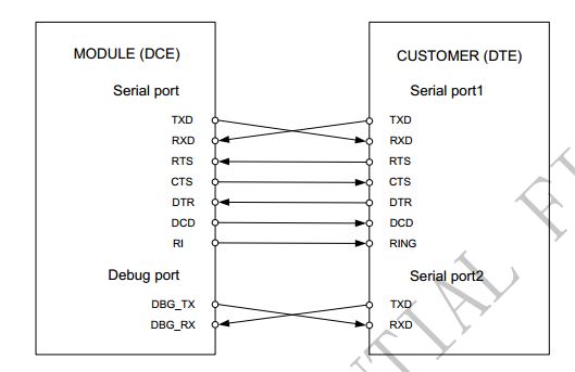
In case no level shifter is required, Which pins should i use in MSP430(DTE) to connect to RTS,CTS, DTR, DCD and RI pins of modem(DCE)?

  • I think i should use GP i/o pins for the connections of RTS, CTS, DTR, DCD and RI. I also found that no level shifter is required.

  • If 'TTL' means 5V high level voltage, then you'll need at least 1k (better 2-10k) series resistor on those pins which output to the MSP.

  • Hello Sir,

    I am doing Project a in which i need to send data to Mobile no through SMS for that i want to interface Ti's MSP-EXP430F5529 Experimenter Board with SIM300 GSM module. My experimental board has USB cable interface. I've been checked about available SIM300 modules in market, I have found out following things from modules -

    I am been trying to find out how can i interface SIM300 module with my project board. 2 ways i can see here onwards ......
    1) RS232 (SIM300) --->to---> USB Converter ---->to----> MSP430F5529 Board
    2) RS 232 (SIM300) --->to---> RS232 to Serial TTL Converter --->to---> SPI bus --->to---> MSP430F5529 Board
    I want to know that which way out of this it will be convenient to me to implement Connectivity ? And also which way it will be easier to us with respect to do CODING in embedded ??
    Also please note that for 1st option Driver should be installed at PC so that Serial interface can communicate with PC. I guess Driver should be installed at board side (Otherwise How come Board will identify that the SERIAL to USB Converter is connected to it !! )
    Thank You,
    With Regards,
    Sunil N Supekar.

    -

  • Sunil Supekar said:
    1) RS232 (SIM300) --->to---> USB Converter ---->to----> MSP430F5529 Board

    That will not  work - that would require the MSP-EXP430F5529 Experimenter Board to be the USB Host.

    Sunil Supekar said:
    2) RS 232 (SIM300) --->to---> RS232 to Serial TTL Converter --->to---> SPI bus --->to---> MSP430F5529 Board

    You would need some "intelligence" to convert Async Serial (RS232) to SPI - it's not just a matter of voltage/pinout conversion.

    But why bother? Why not use the MSP430's UART?

    Look for a module which provides compatible logic-level UART signals; an Arduino "shield" or similar would be a good place to start looking...


  • Karthikeyan Dhandapani said:

    I'm sure SIMCOM are trying to be "helpful" (sic) with this diagram, but note that it is wrong according to the RS232 (V.24) Standard nomenclature!

    The RS232 Standard nomenclature names the circuits - not the pins:

    So TxD is the circuit carrying the data to be transmitted to the comms link by the DCE - so it is an output from the DTE, but an input to the DCE (modem)!

    Similarly,  RxD is the circuit carrying the data received by the DCE from the comms link - so it is an input to the DTE, but an output from the DCE (modem)!

    Unfortunately, this is a very common source of confusion - so SIMCOM are really being rather un-helpful with that diagram!

    To avoid confusion, the only safe way is to read the datasheets carefully and look for the definitions of which pins are inputs and which pins are outputs - do not just assume anything from the pin names!

    V.24 is the ITU equivalent definition of the RS232 signals:

    http://www.itu.int/rec/T-REC-V.24-200002-I/en

    Interchange Circuits:

    CT103 - Transmitted Data:

    .

  • I think that TXd/RXd pins in JP16 of Experimenter Board can be used to connect to the SIM300's UART RXd/Txd (may be wrong). If the voltage levels of UART of sim300 and MSP-EXP430F5529 Experimenter Board are same then there is no need for the RS232 or MAX232. In case you need level transition you can follow sim900 serial port application note v1.03.

    Sunil Supekar said:

    Also please note that for 1st option Driver should be installed at PC so that Serial interface can communicate with PC. I guess Driver should be installed at board side (Otherwise How come Board will identify that the SERIAL to USB Converter is connected to it !! )

    The USB from eZ430 Emulator can be used to connect to computer for application UART. I think the software/driver will be installed in the computer with IAR or CCS. The application UART when connected to computer creates virtual COM port and the USB in computer to which the controller is connected function as serial port which you can use in software such as hyper terminal. There is no need to install software in micro-controller.

  • Andy Neil said:
    I'm sure SIMCOM are trying to be "helpful" (sic) with this diagram, but note that it is wrong according to the RS232 (V.24) Standard nomenclature!

    RS232 (V.24) standard nomenclature ASSumes that you only connect a data terminal with a data communication equipment. (modem). So one side is the terminal, teh oder side of the RS232 line is a transceiver, no the receiver of the data.
    In this case, the direction is clear: TxD goes form the terminal to the transceiver (still TxD), where it is send to another transceiver and turns into TxD for the Terminal at the other side.
    The 'crossover' happens between the two DCEs But here we don't have DCEs at all, we are directly connecting two DTEs. Which is NOT part of the RS232 standard at all.

  • Yes, RS232 is specifically defined as an interface between DTE and DCE - which is why we need a so-called "null modem" for DTE-to-DTE connection.

    But the SIMCOM diagram clearly does show a DTE-to-DCE connection.

  • Karthikeyan Dhandapani said:
    I think that TXd/RXd pins in JP16 of Experimenter Board can be used to connect to the SIM300's UART RXd/Txd (may be wrong).

    The way to verify whether you are right or wrong is:

    1. study the datasheet for the SIM300, and find the specifications for its serial port pins;
       
    2. study the datasheet for the MSP430, and find the specifications for its serial port pins;
       
    3. study the schematics for the MSP-EXP430F5529 Experimenter Board ;
       

    These will tell you whether the voltage levels are compatible.

    This is the general approach to take for any interfacing task: http://www.8052.com/forum/read/160143

    Karthikeyan Dhandapani said:
    If the voltage levels of UART of sim300 and MSP-EXP430F5529 Experimenter Board are same

    They don't actually need to be the same - just compatible.


  • Andy Neil said:
    But the SIMCOM diagram clearly does show a DTE-to-DCE connection.

    I agree that not only the notation of DTE/DCE is superfluous when there is a customer/module marker, it is also wrong in conjunction with the wiring (should be DTE/DTE instead, as this is what it really is.)

  • Jens-Michael Gross said:
    should be DTE/DTE instead, as this is what it really is

    No it isn't - the GSM module is, surely, a DCE; ie, a "modem".

  • Andy Neil said:
    No it isn't - the GSM module is, surely, a DCE; ie, a "modem".

    Ah, you're right. I read it as "GPS module". It's time to leave the office :)

**Attention** This is a public forum