This thread has been locked.

If you have a related question, please click the "Ask a related question" button in the top right corner. The newly created question will be automatically linked to this question.

msp430g2553

Other Parts Discussed in Thread: MSP430G2553

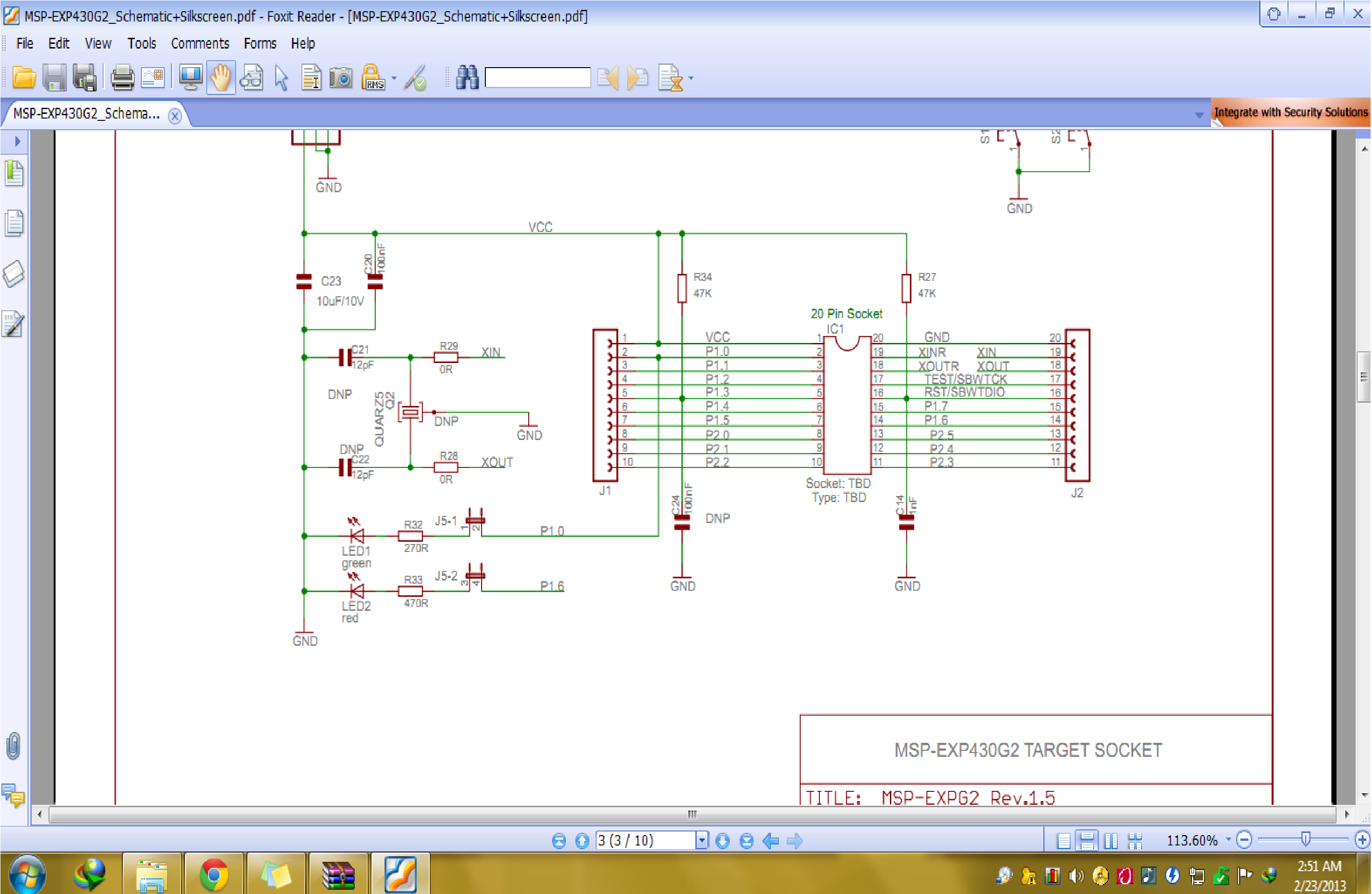
I am using TI launchpad. In the hardware connection of this launchpad(which is shown in TI,s website) the pin no 5 is connected with Vcc using 47k resistor and to GND using 100nF capacitor. But when I am programming the micro controller msp430g2553, the program is running correctly but the voltage at pin 5 is almost 0V. But according to the hardware connection this voltage should have been Vcc. Why this problem is occurring? the link from where i took the reference of hardware connection of msp430g2553 in launchpad is http://www.ti.com/product/msp430g2553. this is the snapshot of hardware connection

regards

Akhilesh Sati

  • Hi Akhilesh,

    That schematic is for revision 1.4 of the launchpad. You've probably got revision 1.5 instead, which does not have an external pullup resistor on P1.3 (pin 5). Also note that the capacitor C24 is marked DNP (Do Not Populate).

    If you want to use pin 5 as an input you can enable the internal pullup resistor by configuring P1REN and P1OUT appropriately. See section 8.2.4 of the MSP430x2xx Family User's Guide for details.

  • Thanks sir for your response.

    the rev 1.5 is having the same configuration as rev1.4. Actually I am pulling the microcontroller out from the launchpad and trying to work with it in breadboard. the schematic that I am following is shown below but the microcontroller is not working with this schematic in breadboard however the same microcontroller is working properly in launchpad. why it is so?

  • First be engineer if you are. Check all components are there in launcpad or not. They are SMD's but still can be seen and read.

    Now Capacitor may or may not be there but does't matter. It still works perfectly.

    Second check voltage 3.6 must on usb. Now check supply on both end to make sure resistor is not faulty and no open ckt.

    Ckt may not work. As it need some essentials to keep it running. Sometimes are forgotten.

       Troubleshooting for you:

    1. Check Vcc on pin 1 gnd on pin 20.

    2. Check Vcc on reset

    3. Must use internal DCO not crystal 32.768 KHz. Declare clock as default may be 32.768 KHz.

    Now check it again and still first check it on board. Sometime it is programming error.

  • Hi,

    I'm not sure what's causing the problem you're getting on the breadboard, but just wanted to point out that the Rev.1.5 schematic is incorrect. I have a Rev.1.5 launchpad and R34 is not present. If you look at the row of SMT components running across the launchpad from the right of the J1 silkscreen label you can see the locations for R34 and C24. Both are unpopulated on my board. I've also verified that there is no connection between pin 5 and GND or VCC (when S2 is not depressed).

    Back to your problem, are you using the launchpad's emulation section to provide power and JTAG/SBW connection to your breadboard for programming? If so, how is the launchpad connected to the breadboard at the moment you test the pin 5 voltage?

  • Paste Your Launchpad Photo Here and You Launchpad must have S2 connected to P1.3 then connect normal large size resistance 47K we use to board. Before solder resistance check S2 is connected to P1.3 and Gnd.

  • thanks for response. the problem is very straightforward. To make the microcontroller program run even if on the launchpad I am using the connections from external 3V battery not from USB. In that circumstances the program is running correctly but when I am taking out the microcontroller and trying to establish the same connections as they are in launchpad i.e.   pin1 to VCC.

                                           pin 20 to GND.

                                           pin 16 to VCC through 47k resistor and GND through 1nF capacitor.

          & I am measuring the voltage at pin 4 i.e.serial port Tx. According to the program this pin 4 should have been HIGH (VCC) & on launchpad it is satisfying this condition but while using the same microcontroller at breadboard, the voltage at pin 4 is coming LOW(GND) & I am not able to understand why it is so?


  • First you tell the problem. Two Reasons. Wrong Hardware or second Wrong software.

    Again Attech Your program ang ckt forget from what you found on net. Just make what used on PCB.

    And If you are not beginner then first try led blinking at 3sec toggle rate or simply send 0X48; and check output. Then move next. Don't go fast.

    I'hv made first ckt but a millions error. It takes 1 week to correct it. Troubleshooting is very lengthy and boring but knowledgefull work.

  • akhilesh sati said:
    I am measuring the voltage at pin 4 i.e.serial port Tx

    Hang on, in the original post you were talking about pin 5 being at 0V, not pin 4.

    Pin 4 is connected to the RXD/TXD pins on header J3. The jumpers on that header connect pin 4 to either BTXD or BRXD depending on their orientation. What positions do you have jumpers installed on J3? Do you have jumpers in place on those header pins when testing with the msp430 fitted to the launchpad?

  • Hello ...Only you need R27 =47 and is optional C14

  • the schematic that i have made on breadboard is follwing..... but using this circuit configuration microcontroller is not transmitting data at it Tx pin

  • How are you detecting whether the MCU is transmitting data? Are you expecting that LED at the top-centre of the picture to light up? Have you tested the LEDs and supporting circuitry to prove that they light up when power is applied? BTW, you may be aware of this, but the LED in the lower-right is not connected up to the same terminal block as the resistor to pin 14.

    Also, please post the program you're using on the MCU (remember to use "preformatted" instead of "paragraph" in the "Format" dropdown menu)

  • Are you expecting that LED at the top-center of the picture to light up?  The answer is YES, this is the only problem that I am facing with this circuit now. The LED on the top is representative of transmitted data using serial port. As far as program that I am using on the MCU is concerned, it is perfectly all right.Even if I have tested the serial port using oscilloscope, I am getting the same data, whatever I am sending through program,BUT this thing is only happening when MCU is on the launchpad. When I am taking the MCU out from the launchpad and making a same circuit on the breadboard and expecting to all the three LEDs to glow in the same manner as they are glowing on the Launchpad. The two LEDs on the bottom are working properly and I have also tested the voltages of all the individual pins of MCU and it is comming same as in case of MCU on launchpad EXCEPT the voltage of the serial port Tx (Pin 4). 

     the LED in the lower-right is not connected up to the same terminal block as the resistor to pin 14. I have corrected this error too still not problem of the serial port Tx is not solved.

  • OK, when you've got the MCU on the launchpad and everything's working, what jumpers do you have installed on header J3? In particular, do you have jumpers on the leftmost two pairs of pins, and what is the orientation of any such jumpers?

  • I think at this point I should re frame my question How to use a programmed MCU outside the Launchpad (I mean what should be the electrical connections if one wants to use a programmed MCU without launchpad).

**Attention** This is a public forum