This thread has been locked.

If you have a related question, please click the "Ask a related question" button in the top right corner. The newly created question will be automatically linked to this question.

Bit Banging Pure Serial Data in C on the MSP430g2553

Other Parts Discussed in Thread: MSP430G2553

Hi Everyone,


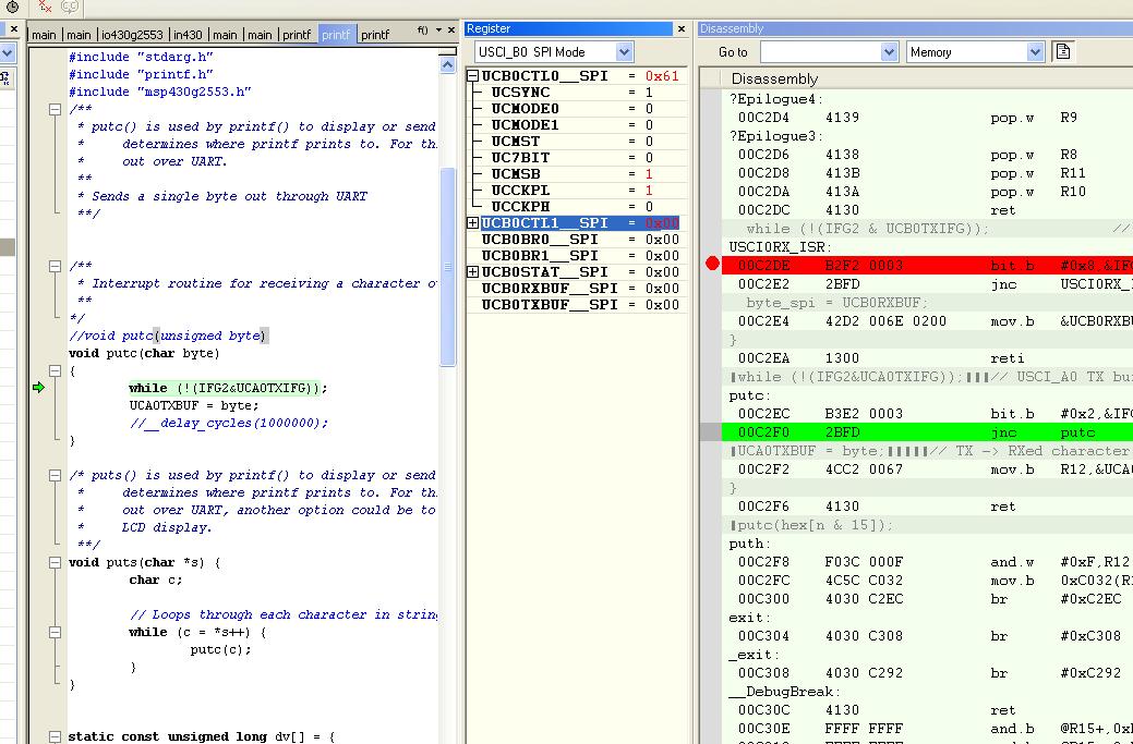
I am working on an RF application using the MSP430g2553.  I have already configured a USCI_AO UART for terminal debugging purposes and am using the "tiny printf" function I found on the launchpad site to print to the terminal.

http://www.msp430launchpad.com/2012/06/using-printf.html

I now have a need for another "serial interface" to receive data coming from my RF IC, preferably on port 2 to avoid conflicts with the current UART configuration.

I have decoded data coming out of my RF IC which I want to pass along to the MSP430 and store into memory to be used later (ie. print to the screen for testing, verifying data, etc.).

The serial data has no start or stop bits, it is simply the raw decoded RF information (128bits repeating themselves cyclically). 

The CLK for the serial data has a period of approximately 250us, so we need to check the DATA line at least every 250us to see if it is a high or a low and store this information in memory.

I found a nice example of a 9600baud bit banged UART on the MSP430 also on the launchpad site:

http://www.msp430launchpad.com/2010/08/half-duplex-software-uart-on-launchpad.html


I had thought about modifying this to use ports on P2 however start and stop bits are not needed and the timing delays for the baud rate certainly don’t match the timing that I require so it seems like this would be way more work than I am prepared to attempt at this point. 

It is important that the data is accurate so I had also thought about embedding interrupts, although If I can get around this without using multiple interrupts it would be nice.  I am assuming that the only way that could be achieved reliably would be by comparing the CLK bits to the DATA bits using another input port.

If I were to go about it using timing interrupts only, this is the way I thought about doing it:

/*

I can implement a timing interrupt that is activated every 250us and check the status of the DATA bit (Port2.7) to see if it is high or a low and then store a ‘1’ or a ‘0’ in the global char array: “byte_decode[127] ”.


Polling only 1 bit gives a high probability for “framing errors” so I’m attempting to poll both the Data and CLK bits.


*/


volatile char byte_decode[8];

volatile unsigned int index2 = 0;


CLK_BIT = BIT5;

DATA_BIT = BIT7;


Void Main()

{

                //Do_something

}


#pragma vector = TIMER_A0_VECTOR
__interrupt 250us_interrupt

{

                If((P2IN  &&  CLK_BIT) != 0)

{             

                If((P2IN && DATA_BIT) == 0)

                Byte_decode[index2] = ‘0’;

                Else()

                Byte_decode[index] = ‘1’;

                Index2++;

}

}             


A problem I am running into is that every time the timer interrupt completes it goes into low power mode and the main function is unable to perform a check to see if the buffer/char array is full or print the array to the terminal.

Could somebody maybe help me out with this or get me headed more in the right direction?


Thanks,
Corin


  • Hi Corin,

    Your code looks to be a mix of actual code and psuedo code, so it's hard to tell why your system is going into low power mode after the timer interrupt.  If you could post all of your code that would help.

    From the way I understand it, your RF IC is generating a clock line (P2.5) and data (P2.7). Another option would be to interrupt off the clock line going high and then in the PORT2 ISR you could check to if the data is high or low and load your array.  This way you are not dependent on the timers of your MSP and the RF IC being in sync.

    HTH,

    Barry

  • Corin Browning said:
    The serial data has no start or stop bits, it is simply the raw decoded RF information (128bits repeating themselves cyclically). 

    In case your RF radio have CLK output, then I suggest to use SPI (slave) on your uC.

    We will see better picture if you tell which RF chip you use.


  • I was under the assumption that neither SPI or I2C would work because the continuous 128bits of serial data does not follow the SPI or I2C protocol.  If I could get this working using USCI_BO that would be great but I don't know if it's feasible.

    There isn't much information at all about the RF IC I am using, I can PM you the chip # and manufacturer if you would like.

  • thanks for your response and input Barry.


    Yes the code I have posted in the first post is just to get you an idea of what I'm trying to do.  I'm trying to pm you my source code as I type this.

  • Corin Browning said:
    SPI or I2C protocol

    SPI protocol? What's that?

    You say - no separate clock line? Just data? Then I wonder how anyone can transmit bits without any NRZ or Manchester or similar coding.

    Corin Browning said:
    I can PM you the chip # and manufacturer if you would like.

    Yes, please. Because what you tell - does not add up.

  • llmars,

    I can utilize a CLK line along with the Data line if necessary.

    Add me as a friend on the TI site so I can send you the IC # and my source code.

    Regards,

    Corin

  • Corin Browning said:
    I can utilize a CLK line along with the Data line if necessary.

    Nice! Then you can use SPI indeed - because it is serial bidirectional interface specification, there's no protocol. In your case only one direction shall be used (RF->uC) and clock (RF->uC), uC shall act as slave which receive clock. 128 bits you can receive as 16 bytes. Please read/check what SPI actually is.

    SPI slave example: msp430g2xx3_uscia0_spi_10.c easy, isn't it? Just don't connect SOMI, don't echo bytes back as in example, but use them.

    Yes I confirmed you.

  • Could anybody else verify llmars statement about SPI?  It would be nice to get a consensus before I spend too many hours on this!

    I'm assuming llmars is correct and I am just about to start modifying msp430g2xx3_uscia0_spi_10.c to work with USCI_B0.  I'm not really expecting anything to happen right off but who knows maybe SPI really isn't too hard after all?

    I'm putting my scope probe on SIMO to see if it tries to send back what it receives (or thinks it's receiving).

    thanks everyone, ill post again soon with updates

    Corin

  • Ilmar is correct. Just google SPI protocol and you will see that it is pretty straight forward. 

    Good luck,

    Barry

  • So I modified the example to work with USCI_B0 (I think).  The only thing that I wasn't able to figure out was what to change the interrupt vector to, so i decided to assume USCIAB0RX_VECTOR was for both USCI_A0 and USCI_B0.

    #include <msp430.h>

    //Modified for USCI_B0


    int main(void)
    {
      WDTCTL = WDTPW + WDTHOLD;                 // Stop watchdog timer
     
      P1REN |= BIT7 + BIT5;
      P1OUT |= BIT7 + BIT5;
     
      while (!(P1IN & BIT5));                   // If clock sig from mstr stays low,
                                                // it is not yet in SPI mode
     
      P1SEL = BIT7 + BIT6 + BIT5;
      P1SEL2 = BIT7 + BIT6 + BIT5;


      UCB0CTL1 = UCSWRST;                       // **Put state machine in reset**
      UCB0CTL0 |= UCCKPL + UCMSB + UCSYNC;      // 3-pin, 8-bit SPI master
      UCB0CTL1 &= ~UCSWRST;                     // **Initialize USCI state machine**
      IE2 |= UCB0RXIE;                          // Enable USCI0 RX interrupt

      __bis_SR_register(LPM4_bits + GIE);       // Enter LPM4, enable interrupts
    }

    // Echo character
    #pragma vector=USCIAB0RX_VECTOR
    __interrupt void USCI0RX_ISR (void)
    {
      while (!(IFG2 & UCB0TXIFG));              // USCI_A0 TX buffer ready?
      UCB0TXBUF = UCB0RXBUF;
    }

    I had to enable pull up resistors in order to get it to work, it's wierd however because the square waves have little notches in them now so they look like little castles (only thing i could think of that resembles the notched square waves).

    The amazing thing is that the UCB0RXBUF_SPI is actually getting filled and there are square waves coming out of SIMO!  I have yet to verify whether the data received into the buffer is valid but this is a great start and I'm surprised at how easy to implement this was.

    Now let's just hope that the data is valid!

  • At 250 nsec per bit, G2553 is not fast enough to do bit banging. SPI is your only chance -- llmas is right.

    Eccentrically, you are using Clock to shift Data into an 8-bit shift register and read that shift register in an ISR after every 8 bits are captured in it.

    For robust operation, you may have to derive a way to re-start you SPI before the arrival of each RF packet. There may be a prolonged period of no Clocks between packets. The RF chip may also provide other clues.

  • Right now I am trying to store the rx buffer into a *char and then collect all 16 bytes so I can view all 128bits and verify they are valid. Should I do this outside the interrupt or inside the interrupt? 

  • Corin Browning said:
    Should I do this outside the interrupt or inside the interrupt?

    It depends. One can do all the calculations and not only, in IRQ, but you shall know what you do. Usually rule is: gather data using IRQ but process data outside it, in main application code. When data buffer completely received - use global volatile variable for signalling between IRQ and main code.

  • It does not matter.

  • old_cow_yellow said:
    It does not matter.

    It does - If verification is so long that you miss next IRQ and lose data in result.

  • Corin Browning said:
    Right now I am trying to store the rx buffer into a *char and then collect all 16 bytes so I can view all 128bits and verify they are valid.

    One thing that puzzles me is this....

    How do you plan to get the bits to align on the proper byte boundaries? It seems like you have just clock and data. What if the bits are all shifted by, say, 3 bits?

    Just something to keep in mind and think about. Some manipulation of the captured data may be necessary. Is there a protocol header that you can use as the basis of a software correlator?

  • Brian Boorman said:

    Right now I am trying to store the rx buffer into a *char and then collect all 16 bytes so I can view all 128bits and verify they are valid.

    One thing that puzzles me is this....

    How do you plan to get the bits to align on the proper byte boundaries? It seems like you have just clock and data. What if the bits are all shifted by, say, 3 bits?

    Just something to keep in mind and think about. Some manipulation of the captured data may be necessary. Is there a protocol header that you can use as the basis of a software correlator?

    [/quote]

    Yes there is a header that consists of 10 0's followed by a 1 which will allow me to determine where the 128 bits of data start.
    -----------------------------------------------------------------------------------------------------------------------------------------------------------------

    Right now I am having the issue that whenever I try to set a char equal to UCB0RXBUF, whether it's a volatile global variable used in the interrupt or a local variable used in main, I keep getting this weird error:

    Error{Pe513]: a value of type "unsigned char" cannot be assigned to an entity of type "unsigned char"

    Does anyone know why this is happening and how I can set a variable equal to the received buffer?

    Thanks,
    Corin

  • Corin Browning said:
    Error{Pe513]: a value of type "unsigned char" cannot be assigned to an entity of type "unsigned char"

    Are you sure there isn't a "*" in one of those "unsigned char" portions of the error?

    PE513 usually comes about because of type mismatching. Can you post the offending line of code and the matching variable definition?

  • Brian Boorman said:
    How do you plan to get the bits to align on the proper byte boundaries? It seems like you have just clock and data. What if the bits are all shifted by, say, 3 bits?

    SPI slave usually have CS (chip select) line which is used to reset SPI engine of slave to initial state.

    Your have continuous data bitstream? - Then you have to treat incoming 8-bit data as bits and find 128-bit frame in it by looking for frame start bit pattern or something like that.

  • Correction: I'm able to do it inside the interrupt with a global variable but not outside the interrupt.

    I haven't gotten a chance to work on it today very much unfortunately because we had other things going on at work, also I am getting a prototypical board layout finished. 

  • Ilmars said:

    How do you plan to get the bits to align on the proper byte boundaries? It seems like you have just clock and data. What if the bits are all shifted by, say, 3 bits?

    SPI slave usually have CS (chip select) line which is used to reset SPI engine of slave to initial state.

    Your have continuous data bitstream? - Then you have to treat incoming 8-bit data as bits and find 128-bit frame in it by looking for frame start bit pattern or something like that.

    [/quote]

    Yes continuous 128bit bit stream. 

    What do you mean by treating them as bits, by converting each char to binary?  If so how would one do this?  It would probably have to be after all 16bytes are collected.  Right now I'm trying to store all 16 chars in an array and then I was thinking about checking for a 0x00 (or maybe two 0x00 hex values) to find the beginning of the bit pattern.  

  • Corin Browning said:
    What do you mean by treating them as bits

    .. as continuous bit sequence which is passed to your application (SPI IRQ) as "chunks" of 8 bit words, without alignment.

    Corin Browning said:
    If so how would one do this?  It would probably have to be after all 16bytes are collected

    You need to do frame header search continuously - during receive. Easy and more or less trivial way is: shifting and bit-comparing to known bit pattern bit by bit until complete match.

    BTW how would you detect frame in bit-banging approach?

  • Corin Browning said:

    Right now I am trying to store the rx buffer into a *char and then collect all 16 bytes so I can view all 128bits and verify they are valid. Should I do this outside the interrupt or inside the interrupt? 

    Inside or outside ISR, you are viewing those data that have already stored. Either way you are ignoring data that arrived before/after those stored data.

  • I am having an issue with the UART now which I think is related to the SPI configuration.  At the very beginning of main after intializing clocks and the UART I have a line of code:

    printf("test");

    Only the first "t" and "e" are sent to the terminal.  After this it gets stuck in the printf function at this point:

    void putc(char byte)
    {
        while (!(IFG2&UCA0TXIFG));            // USCI_A0 TX buffer ready?
        UCA0TXBUF = byte;                    // TX -> RXed character
        //__delay_cycles(1000000);
    }

    It's interesting that it prints the first two characters but gets stuck in the printf function after that. 

    I'm thinking this line:

    while (!(IFG2&UCA0TXIFG));          

    needs to be changed to take into account the SPI settings.  Anybody have any idea why it is doing this?

**Attention** This is a public forum