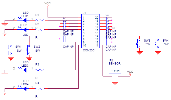
i hav configured uC for 1mhz frequency and then transmitted some code on p2.1 for ir remote control application. I also hav ir receiver tsop1738 connected to the board.
Output of sensor is captured in through p2.3 (CCIOB) for timer1_A3. After I transmit some code ,i configure the timer in capture mode and expect uC to receive it and then it shoud stop operation, but
" it is transmitting code cotinuously and not at all receiving anything" i.e. it might be resetting continuously.
my code is given below:
#include "msp430g2553.h"
//#include "bool.h"
#define LED_OFF LED_OUT &= ~LED_1
#define LED_ON LED_OUT |= LED_1
#define LED_OUT P2OUT
#define LED_1 BIT1
#define LED_DIR P2DIR
void tx_bit(short);
short int frame,intr_count,frame_rec;
void uart_init();
unsigned int irlength;
void main()
{
short int k,bitval;
//stop watchdog
WDTCTL = WDTPW + WDTHOLD;
//setup internal DCO
BCSCTL1 = CALBC1_1MHZ;
DCOCTL = CALDCO_1MHZ;
//General GPIO Defines
LED_DIR |= LED_1 ; // Set P2.1 to output direction AND 2.3 INPUT
LED_OFF; // Set the LEDs off
P1DIR =0XFF;
P1OUT =0X00;
frame =0x61;
//tx_start();
__delay_cycles(5000);
for(k=0;k<8;k++)
{
short int m;
m=k;
if(frame & (0x01 << m))
{
bitval=1;
}
else
{
bitval=0;
}
tx_bit(bitval);
}
tx_bit(0);
//wait
__delay_cycles(500);
// P1OUT |= BIT4;
P2SEL |= BIT3; // P2.1 TA1/2 options
P2SEL2 &= ~BIT3;
TA1CTL = TASSEL_2 + ID_3 + MC_2 + TAIE; // TIMER INiTiLIZATION
TA1R = 0X0000;
TA1CCTL0 = CM_2 + CCIS_1 + CAP + CCIE;
intr_count=0;
uart_init();
__enable_interrupt();
//_BIS_SR(LPM0_bits + GIE); // LOW POWER MODE
while(intr_count<9);
//frame is received
TA1CCTL0 &= ~CCIE; //RECEIVE INT disabled
TA1CTL |= MC_2; //timer stopped
}
/*void tx_start()
{
int i;
for (i=0;i<960;i++)
{
//40 Khz Carrier generation. 25us pulse time
//9us On and 16us off
//96 pulses in one start bit time
LED_ON;
__delay_cycles(6);
LED_OFF;
__delay_cycles(10);
}
__delay_cycles(3200); //600us delay
}
*/
void tx_bit(short bitval) //just makes a 1 to 0 and vice versa
{
int i=0;
switch (bitval)
{
case 0:
for (i=0;i<308;i++)
{
//40 Khz Carrier generation. 25us pulse time
//9us On and 16us off
LED_ON;
__delay_cycles(6);
LED_OFF;
__delay_cycles(10);
}
__delay_cycles(32000); //600us delay
break;
case 1:
for (i=0;i<385;i++)
{
//40 Khz Carrier generation. 25us pulse time
//9us On and 16us off
LED_ON;
__delay_cycles(6);
LED_OFF;
__delay_cycles(10);
}
__delay_cycles(40000); //600us delay
break;
}
}
#pragma vector = TIMER1_A0_VECTOR
__interrupt void timer1_cap_isr(void)
{
/* if(TA1CCTL0 & 0x8000)
{
TA1CTL |= MC_0;
TA1R = 0X0000;
TA1CTL |= CM_1 + MC_2;
}
else
{
TA1CTL |= MC_0;
TA1CTL |= CM_2 + MC_2;
irlength = TA1CCR0; */
P1OUT |= BIT6;
TA1CTL |= MC_0;
TA1R = 0X0000;
TA1CTL |= MC_2;
irlength = TA1CCR0;
if(intr_count != 0)
{
if (6000 < irlength && irlength < 7000)
{
P1OUT |= BIT0;
frame_rec |= (0x01 << (intr_count -1));
}
else if(4625 < irlength && irlength < 5625)
{
P1OUT &= ~BIT0;
frame_rec = frame;
}
else
{
P1OUT &= ~BIT0;
}
}
intr_count++;
if(intr_count == 9)
{
intr_count = 0;
while (!(IFG2&UCA0TXIFG));
UCA0TXBUF = frame_rec;
LPM0_EXIT;
}
}
void uart_init()
{
P1SEL |= BIT1 + BIT2 ; // P1.1 = RXD, P1.2=TXD
P1SEL2 |= BIT1 + BIT2 ; // P1.1 = RXD, P1.2=TXD
P1DIR |=BIT0;
// P1OUT &= ~BIT0;
UCA0CTL1 |= UCSSEL_2 + UCRXEIE; // SMCLK
UCA0BR0 = 104; // 1MHz 9600
UCA0BR1 = 0; // 1MHz 9600
UCA0MCTL = UCBRS1; // Modulation UCBRSx = 1
UCA0CTL1 &= ~UCSWRST; // **Initialize USCI state machine**
//IE2 |= UCA0RXIE; // Enable USCI_A0 RX interrupt
}
why such thing is happening? can anybody tell me?
my hardware: